
LED ramping circuit

This circuit effectively utilizes the 555 timer ICs to create a dual-frequency output necessary for modulating the brightness of the LED. The first 555 timer (IC1) generates a high-frequency square wave at 10 kHz, which is essential for rapid switching, while the second timer (IC2) produces a low-frequency square wave at 1 Hz, which dictates the overall modulation speed of the LED brightness.
The LM393 operational amplifier acts as a comparator, receiving the outputs from both timers. The comparator's role is to compare these two frequency signals and generate a pulse-width modulation (PWM) output. This PWM signal varies in duty cycle, which directly influences the average power delivered to the LED.
Field-effect transistor Q1 is employed to handle the higher current required by the LED. The PWM signal from the LM393 controls the gate of Q1, allowing it to switch the LED on and off rapidly. The result is a smooth transition in brightness, as the LED ramps up to full brightness and then dims back to OFF. The time constants of the 555 timers, along with the resistor R4, can be adjusted to fine-tune the LED's brightness ramping speed and overall current flow, ensuring optimal performance and longevity of the LED.
This circuit design is particularly useful in applications requiring visual indicators with gradual brightness changes, such as in decorative lighting, automotive lighting, or user interface elements in electronic devices.In this circuit the intensity of LED will vary in a ramping fashion. The circuit consists of three ICs: Two 555 timer ICs and one LM393 op-amp. IC1 and IC2 are wired as oscillators to produce 10 KHz and 1 Hz frequencies respectively. These two frequencies are given to the inputs of the op-amp LM393. LM393 is wired as a comparator and its output will be a PWM signal. This PWM signals controls the FET Q1 to drive the LED. The LED will rise from OFF state to full brightness slowly and then slowly fades to OFF state and this operation repeats. The resistor R4 controls current through the LED. 🔗 External reference
Related Circuits
Various sawtooth voltage generators utilize the principle of capacitor charging and discharging to produce sawtooth waveforms in both forward and reverse directions. A simple sawtooth voltage generator circuit is straightforward in design; however, it suffers from poor linearity in...
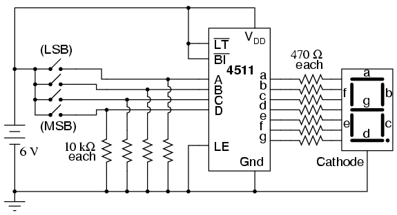
Digital circuits are circuits that handle signals restricted to binary states of zero and a maximum value. This is in contrast to analog circuits, where signals can vary continuously within the limits set by power supply voltage and circuit...
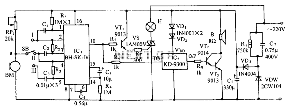
The circuit includes a microphone transducer, voice circuits, an SCR control circuit, a vocal music buck rectifier circuit, and an AC circuit. The BH-SK-IV serves as the core of the device. The described circuit is a complex assembly designed to...
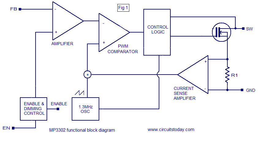
The MP3302 is a boost converter integrated circuit (IC) specifically designed for LED drive applications. It is capable of driving 27 LEDs, arranged as 9 strings of 3 white LEDs in series, powered by a lithium-ion battery. The IC...

This circuit describes the sensing of air flow using the PIC16C781 microcontroller. It utilizes Programmable Switch Mode Controllers (PSMC) that combine an Integrated Operational Amplifier, a Digital-to-Analog Converter (DAC), and a gated timer to create a thermally operated air...
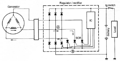
The circuit of the Suzuki GSX1300 Hayabusa charging system consists of a generator, a regulator/rectifier unit, and a battery. The alternating current (AC) generated by the generator is rectified by the rectifier to produce direct current (DC), which is...