
Very low frequency generator

The Wien bridge oscillator is a type of electronic oscillator that produces sine waves. It is based on a bridge circuit that includes resistors and capacitors arranged in a specific configuration. The oscillator operates by balancing the bridge circuit, allowing it to generate a stable frequency output.
In this design, the frequency range is specified to start at 1 Hz and extend to 20 Hz, with the ability to tune in 2 Hz steps. This is achieved by adjusting the values of the resistors and capacitors in the bridge circuit. The frequency can be fine-tuned for applications requiring precise frequency generation, such as in audio testing or signal processing.
The output amplitude is specified as a maximum of 3 volts RMS, which corresponds to 8 volts peak-to-peak. This output level is suitable for a variety of applications, including driving other circuits or providing a reference signal.
To facilitate flexibility in output level, a potentiometer (variable resistor) combined with a switch is incorporated into the design. This allows for precise attenuation of the output signal, enabling the user to set the output level to any desired value within a range of 5 decades. This feature is particularly useful for applications requiring varying signal strengths or for interfacing with other equipment that may have different input sensitivity requirements.
Overall, the Wien bridge oscillator with an adjustable output level provides a versatile solution for generating low-frequency sine wave signals with high precision and control.Wien bridge oscillator generates frequencies of 1 Hz and 2 to 20 Hz in 2 Hz steps. Maximum output amplitude is 3 volts rms of 8 volts peak-to-peak A pot-and-switch attenuator allows the output level to be set with a fair degree of precision to any value within a range of 5 decades.
Related Circuits
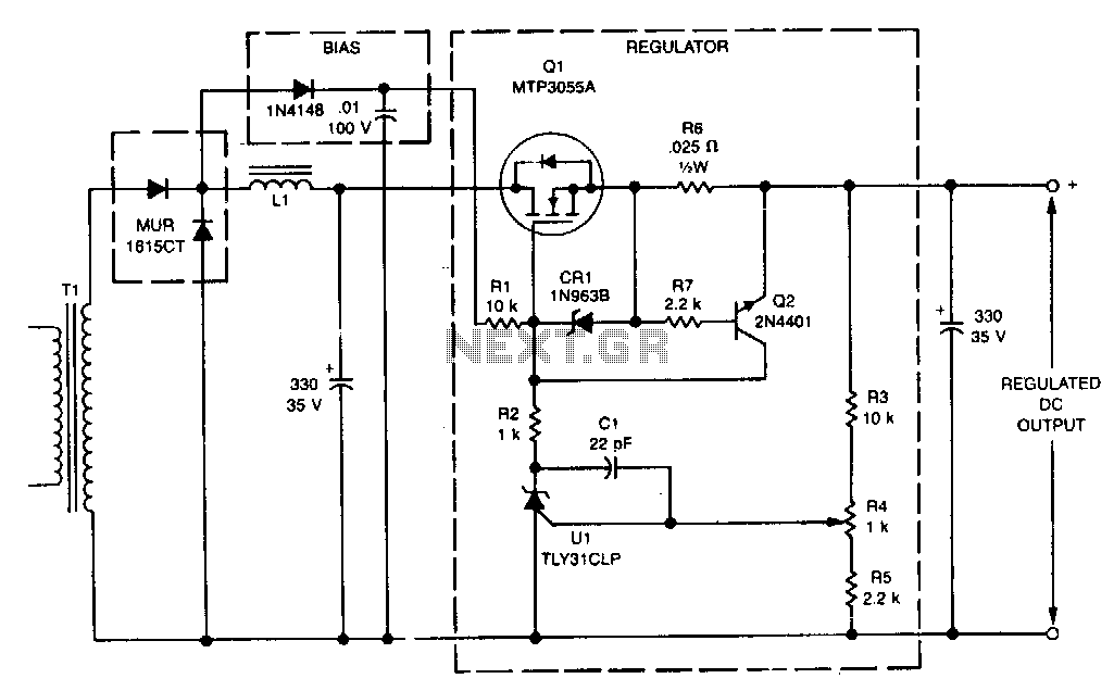
This linear post regulator provides 12 V at 3 A. It utilizes the TL431 reference (U1), which, without additional amplification, drives the gate of the TMOS MTP3055A (Q1) series pass regulator. A bias voltage is applied through resistor R1...
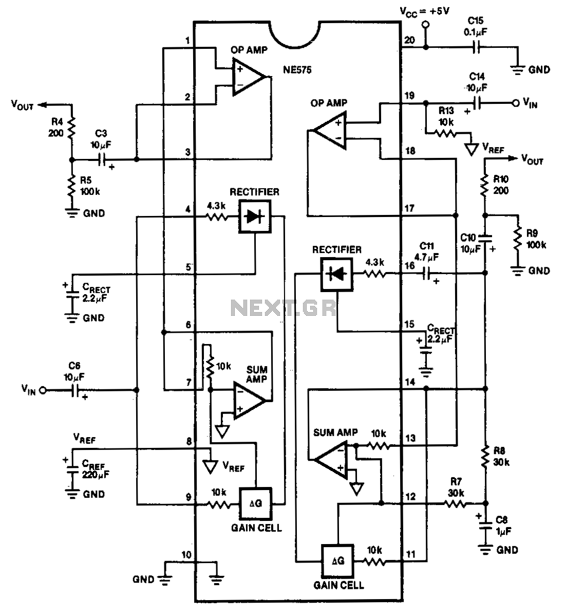
The NE575 is a dual-gain control circuit designed for low voltage applications. Channel 1 acts as an expander, while Channel 2 can be configured for expander, compressor, or automatic level controller (ALC) applications. The NE575 dual-gain control circuit is specifically...
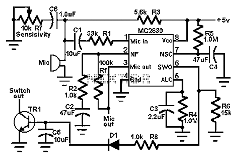
The circuit schematic utilizes the MC2830 voice circuit. Traditional voice circuits are unable to differentiate between speech and noise in the input signal. In noisy environments, such as those caused by switches, this limitation is significant. To address this...
The voltage to frequency converter (V/FC - VCO) circuit consists of a UJT (uni-junction transistor) oscillator in which the timing charge capacitor C2 is utilized. The voltage to frequency converter circuit operates by converting an input voltage into an output...
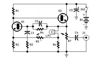
Set R5 to read 1V RMS on an audio millivoltmeter connected to the output with R7 rotated fully clockwise, or to view a sine wave of 2.828V peak-to-peak amplitude on the oscilloscope. An audio amplifier is an electronic device...
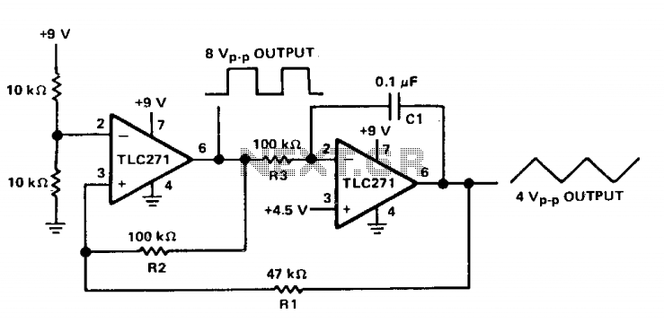
The circuit features both square-wave and triangle-wave outputs. The left section operates similarly to a comparator circuit that employs positive feedback for hysteresis. The inverting input is biased at half the Vcc voltage using resistors R4 and R5. The...