
Voltage to Frequency Converter Using UJT

The voltage to frequency converter circuit operates by converting an input voltage into an output frequency. In this design, a UJT oscillator is employed, which is known for its simplicity and effectiveness in generating oscillations. The UJT is characterized by its three terminals: the emitter (E), and two base terminals (B1 and B2).
The timing capacitor, C2, plays a crucial role in determining the frequency of oscillation. As the input voltage varies, it influences the charge and discharge cycles of C2. The UJT oscillator operates by charging C2 through a resistor until the voltage across C2 reaches a certain threshold, at which point the UJT turns on, discharging C2 rapidly and generating a pulse. This cycle repeats, producing a continuous output frequency that corresponds to the input voltage level.
The frequency output can be adjusted by varying the resistance in the charging path or by changing the capacitance value of C2. This flexibility allows for a wide range of frequency outputs based on the input voltage, making the V/FC circuit suitable for various applications, including signal processing and frequency modulation.
Overall, the UJT oscillator configuration in the voltage to frequency converter circuit provides a straightforward and efficient method for frequency generation based on varying input voltage levels.The following voltage to frequency converter (V/FC - VCO) circuit consist of a UJT (uni-junction transistor) oscillator in which the timing charge capacitor C2.. 🔗 External reference
Related Circuits
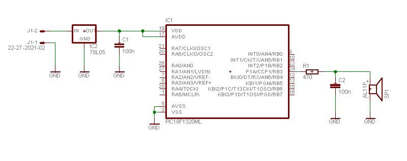
This project enables a PIC microcontroller to play audio PCM sounds using PWM modulation. Pulse-code modulation (PCM) is a digital representation of audio signals. The project utilizes a PIC microcontroller, which is programmed to generate audio signals through pulse-width modulation...
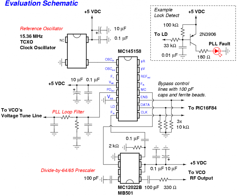
The Motorola MC145158 is a dual-modulus, serial-input PLL frequency synthesizer commonly utilized in older Motorola cellular phones. For detailed technical specifications, refer to the MC145158 datasheet. Although the MC145158 is no longer in production, it can occasionally be found...
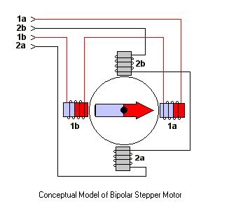
The ULN2003 features high voltage, high current Darlington arrays, each consisting of seven open collector Darlington pairs with common emitters. The ULN2003 is a versatile integrated circuit designed for driving high-current loads such as relays, motors, and lamps. It...
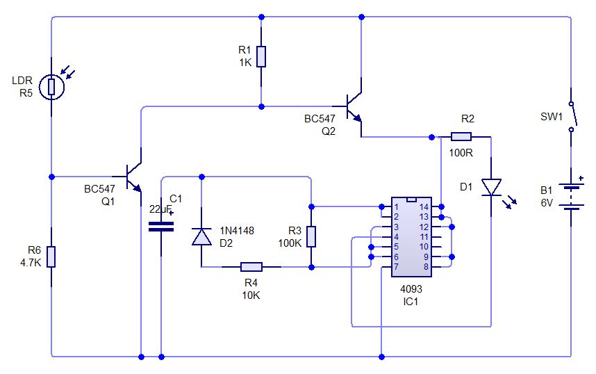
This is a simple experiment involving a Light Dependent Resistor (LDR) and a CD4093 integrated circuit. It modifies a previous dark sensor project that utilized two transistors. In this configuration, when light falling on the LDR is obstructed, the...
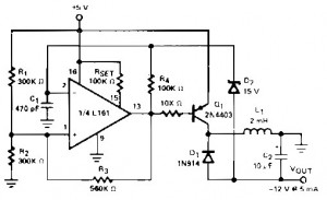
A regulated DC to DC converter utilizing the Micro Power Quad Comparator L161 integrated circuit, which features ultra-low power consumption. This circuit is designed to convert 5V DC to 12V DC at a current output of 5mA. The circuit employs...

The difference between instantaneous frequency and central frequency of the carrier is directly proportional to the instantaneous value of the amplitude of the message signal. A 555 Timer configured in Astable Mode can be utilized for generating Frequency Modulated...