
Colpitis oscillator

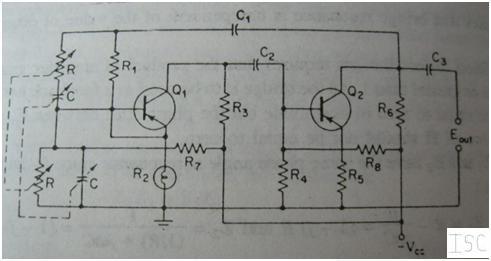
The circuit utilizes a PNP bipolar transistor, which requires a proper biasing arrangement to operate effectively. The resistor voltage divider formed by R1 and R2 establishes a stable bias voltage at the base of the transistor, ensuring that it remains in the active region during operation. This configuration is essential for achieving the desired amplification characteristics and maintaining linearity in the signal processing.
Capacitor C5 plays a critical role in maintaining the collector at AC ground potential. By connecting C5 between the collector and ground, AC signals are allowed to pass while DC conditions are preserved, thus preventing any unwanted DC biasing effects from influencing the output signal. The placement of C5 close to the transistor minimizes parasitic inductance and capacitance, which can adversely affect high-frequency performance.
The feedback mechanism is implemented through the capacitor voltage divider formed by C2 and C3. This arrangement allows a portion of the output voltage to be fed back to the input, enhancing the stability and response of the oscillator circuit. The values of C2 and C3 can be adjusted to modify the feedback ratio, thus influencing the overall gain and frequency response of the circuit. This feedback loop is crucial for sustaining oscillations and ensuring consistent performance across varying operating conditions.
Overall, the combination of the resistor voltage divider for biasing, the AC grounding capacitor, and the feedback network forms a robust and efficient oscillator circuit suitable for various applications in electronics.Bias for the pnp bipolar transistor is provided by resistor voltage divider network R1/R2. The collector of the oscillator transistor is kept at ac ground by capacitor C5, placed close to the transistor. Feedback is provided by capacitor voltage divider C2/C3.
Related Circuits
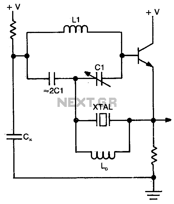
This circuit operates at or near series resonance. It is a well-designed circuit with no parasitics. It is easy to tune and has good frequency stability. The circuit in question utilizes series resonance to achieve optimal performance. At series resonance,...
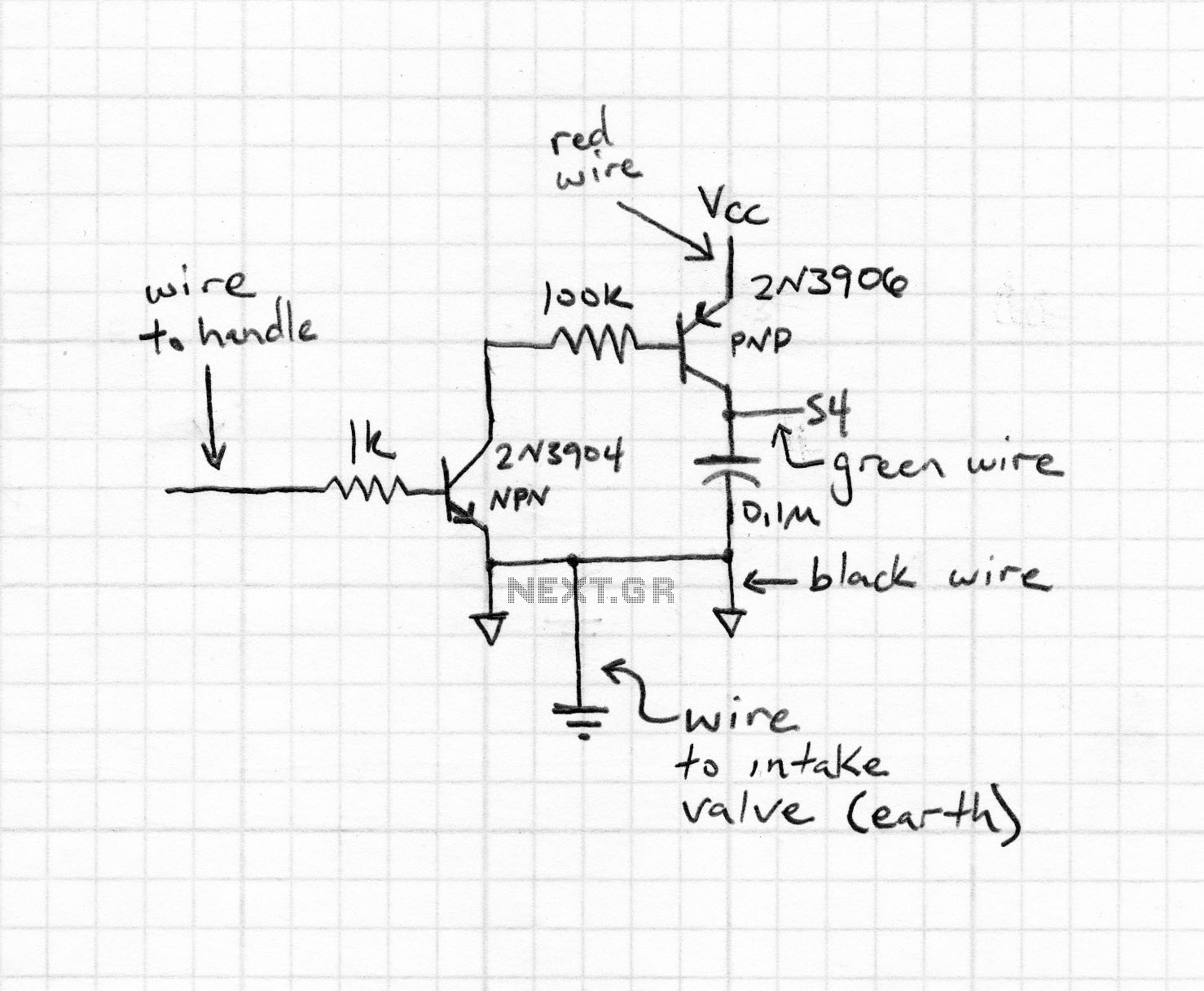
Zener diodes were utilized to derive a stabilized voltage for the Hartley oscillator. While sorting through a box of valves, suitable voltage stabilizer valves (CV287) were discovered. During this process, the ECC81 utilized in the local oscillator was noted...
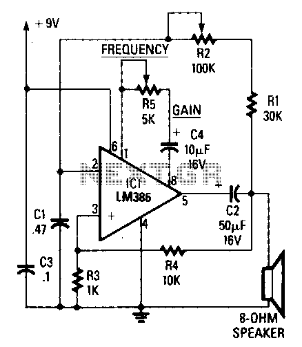
The circuit's frequency of oscillation is given by the formula: f = 2.8 / [C1 x (R1 + R2)]. By adjusting the potentiometer R2, the output frequency can be varied from 60 Hz to 20 kHz. A portion of...
This article explains the construction and working of feedback oscillators, with a detailed description of the Wien bridge oscillator and phase shift oscillator, along with their circuit diagrams, basic components, and practical applications. Oscillators are electronic devices that produce...
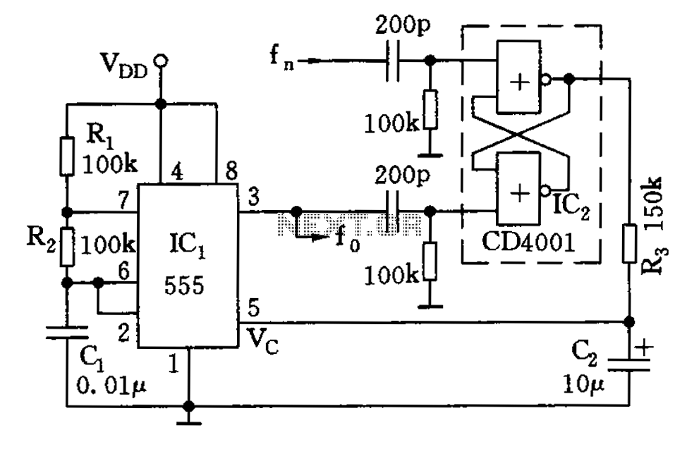
The circuit illustrated consists of a 555 timer along with resistors R1 and R2, and capacitor C1, forming a composition-controlled multivibrator. The oscillation frequency is influenced not only by the RC time constant but also by the adjustment of...
This oscillator is a variation of the oscillator presented by Ulrich L. Rohde, DJ2LR, in his article "Evaluating Noise Sideband Performance in Oscillators," published in Ham Radio, October 1978, Page 51. The original circuit can be found at the...