
VGA to video converter
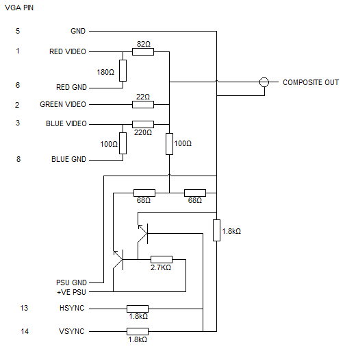
The circuit for generating greyscale video from a VGA source involves several key components and connections. The primary function is to convert the VGA output into a format compatible with standard television displays. This is achieved by processing the RGB signals from the VGA output, where the red, green, and blue signals are combined to create a single greyscale output. The first circuit is responsible for this conversion, ensuring that the video signal adheres to the necessary timing specifications for television compatibility.
The second circuit provides the composite sync signal, which is essential for synchronizing the video output with the television's display. This circuit generates the horizontal and vertical sync pulses that are necessary for proper image rendering. The integration of these sync signals with the video output is crucial, as it aligns the generated video frames with the television's refresh cycle.
To enable the VGA adapter to operate with PAL or NTSC timings, a specific driver must be installed on the computer. This driver adjusts the timing of the VGA output to match the television standards, allowing for successful synchronization. The outdated driver mentioned in the description includes a circuit diagram that can serve as a reference for constructing the necessary hardware. The availability of a newer driver ensures that users can benefit from improved compatibility and performance.
Power supply considerations are also important in this setup. The circuit can function with different voltage levels, such as 5V or 12V, providing flexibility for various applications. The use of a 9V PP3 battery for portable applications demonstrates the adaptability of the circuit design. For permanent installations, accessing the power supply from a computer is a practical solution, allowing for a clean and efficient setup.
In summary, this circuit setup effectively converts VGA signals to greyscale video for television displays, utilizing composite sync for synchronization. The requirement for a specific driver and the flexibility in power supply options enhance the usability of the design, making it suitable for both temporary and permanent implementations. For color output, a more complex circuit involving integrated circuits would be necessary, expanding the capabilities of the VGA to television conversion process.I used the first circuit to generate the greyscale video, and mixed in the composite sync obtained from the second circuit, I had tried just mixing in the Hsync and Vsync as per the first circuit but couldn`t get this to sync the TV. The adapter itself is no use without a driver on the computer to force the VGA adapter to use PAL/NTSC timings, the
vgatv link explains the concept, but basically VGA is at a higher screen refresh than a tv signal, and needs to be slowed down to the right frequency. The driver above is out of date, but has the aforementioned circuit diagram in the help file. A newer version of the driver is available here there is also a windows driver available too. This driver works fine with my modified circuit, the video is only greyscale of course, for colour you`d need to build the complex circuit with ICs.
The +ve PSU pin can be whatever voltage you have available, it definitely works with 5v and 12v, and I am currently using the adapter with a battery clip and 9v PP3 battery to avoid needing another PSU, if you were using the circuit on a PC all the time you could easily bring the 0 and 5v lines out from a spare plug on your computer power supply through one of the many dust collection holes PCs seem to have! 🔗 External reference
Related Circuits
Given the variety of equipment in modern home entertainment systems, the ability to adjust the gain of both audio and video signals has become essential. This particular circuit has proven to be very useful when used alongside the General...
The VFC110 chip can be utilized to construct a high-frequency voltage-to-frequency converter. This chip features high-frequency operation capability, a disable function, and an on-board precision 5V reference. This precision reference can serve to offset the VFC transfer function and...
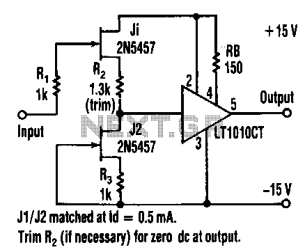
This buffer amplifier's overall harmonic distortion is low at 0.01% or less at a 3-V RMS output into a 500-ohm load without overall feedback. The LT1010CT features a slew rate of 100 V/µs, a video bandwidth of 20 MHz,...
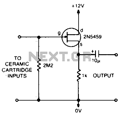
This circuit matches the very high impedance of ceramic cartridges, providing unity gain and low impedance output. By "loading" the cartridge with a 2.2MΩ input resistance, the cartridge characteristics are adjusted to closely compensate for the RIAA recording curve....
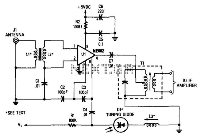
In this configuration, the NE602 serves as a frequency converter in a superheterodyne front-end setup. L1 and L2 form a broadband toroidal transformer, although a tuned transformer may also be utilized. The supply voltage ranges from +5 to +9...
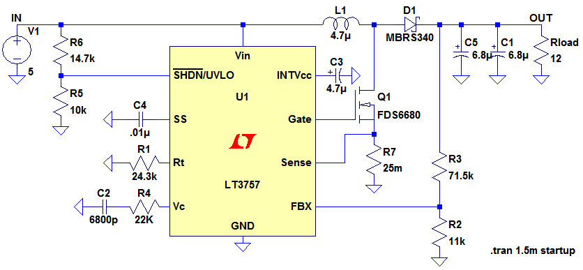
Ignore components C1, C2, R3. The MOSFET, Q1, switches on, creating a short circuit between the right-hand side of the inductor, L1, and ground (0V). A fixed voltage of 3.3V is applied across the inductor, causing its current to...