
vgavideo adapter circuit schematic

In a VGA system, the synchronization signals are crucial for maintaining the integrity of the image being displayed. The vertical synchronization (VSYNC) signal indicates the start of a new frame, and timing the data exchange correctly is essential to ensure that the data is processed and displayed without distortion.
The UART (Universal Asynchronous Receiver-Transmitter) interface is commonly used for serial communication between devices. When integrating UART with VGA, it is important to adhere to specific timing requirements to ensure that the data is transmitted and received accurately. The recommendation to wait 300-600 microseconds after the VSYNC signal serves to allow sufficient time for the system to stabilize before data is sent.
During this interval, the system can prepare the necessary data for transmission, ensuring that it aligns with the current frame being displayed. This timing also helps to mitigate any potential latency issues that could arise from sending data too close to the VSYNC signal, which could lead to image artifacts or flickering.
In practical applications, this timing can be implemented using a timer or a delay function in the firmware of the microcontroller or processor managing the UART communication. By carefully managing the timing of data transmission in relation to the VSYNC signal, the overall quality of the VGA output can be significantly improved, leading to a clearer and more stable image on the display.To avoid distortion of the image, when receiving data through the UART, for VGA, it is recommended to make the data exchange with the terminal in approximately 300-600 us after a signal of vertical synchronization (VSYNC). 🔗 External reference
Related Circuits
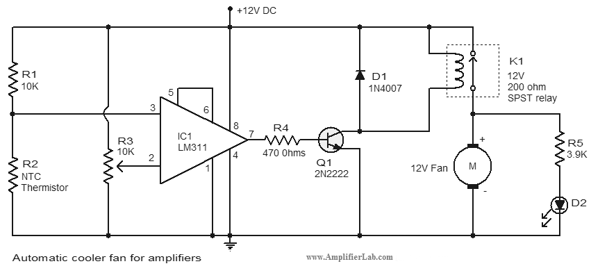
An automatic cooler fan for amplifiers is a circuit designed to conserve power in amplifier circuits. This circuit activates the fan. The automatic cooler fan circuit for amplifiers operates by utilizing temperature sensors to monitor the heat generated by the...
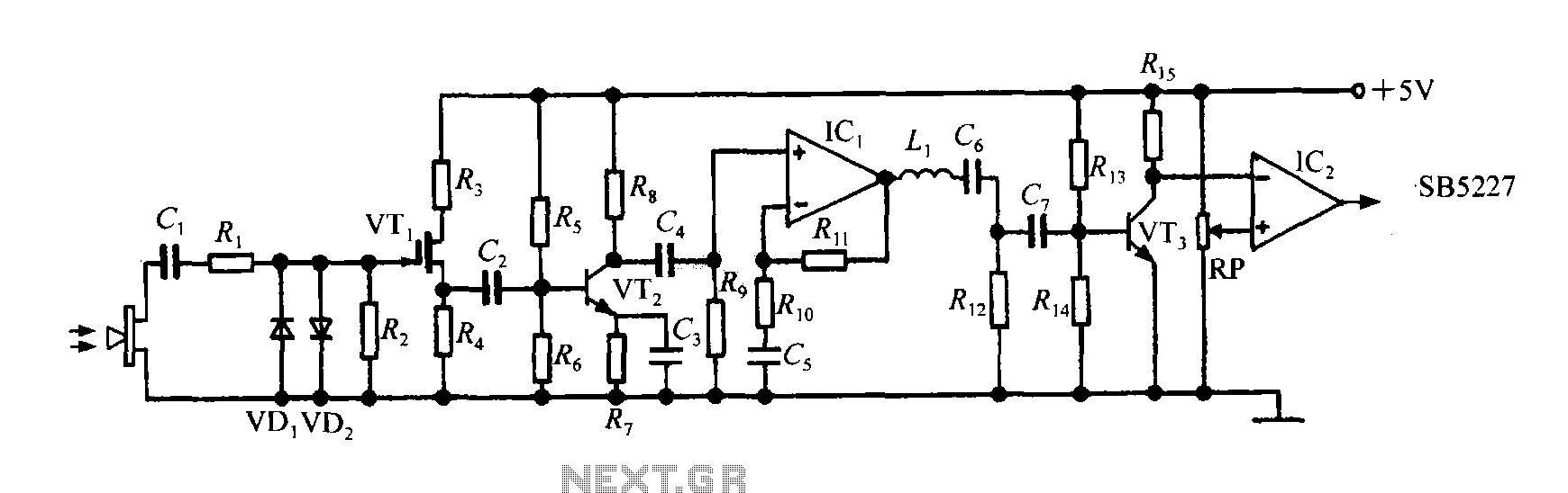
The SB5227 ultrasonic signal output is very weak and must be amplified via a power amplifier for effective transmission. A typical transmission circuit is illustrated in the accompanying figure. The SB5227 ultrasonic signal is sourced from output pin 10,...
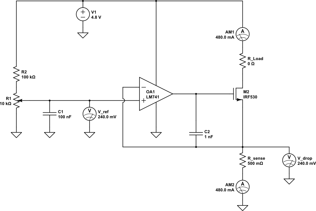
A current limiting circuit is designed to select a maximum current through a load, set to a maximum of 480 mA. As the load resistance increases, the series equivalent resistance (SER) of the limiting circuit decreases. When charging a...
WB5LUA described GaAsFET preamplifiers for several microwave bands, which included an active bias circuit for the GaAsFET. Although newer devices have been introduced that offer improved performance, they require different bias points with varying currents and voltages. Modifying the...
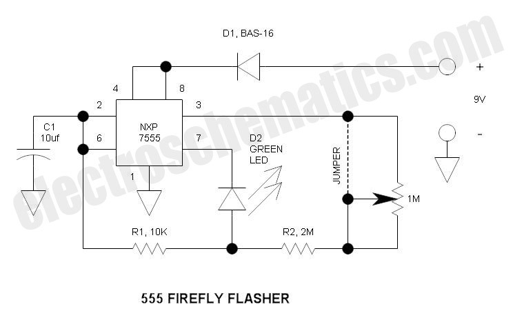
This circuit operates similarly to a standard 555 astable timer, with the distinction that the LED is integrated into the capacitor reset path. Consequently, when pin 7 discharges capacitor C1 to ground, a relatively high current flows through the...
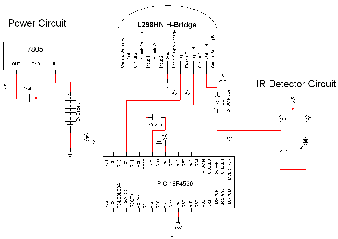
The simple motor optical encoder circuit is not particularly difficult; however, it requires careful verification to ensure all connections are correct before initial operation. The primary components utilized in the circuit include the 7805 voltage regulator, the PIC18F4520 microcontroller,...