
vhf ampand transmiter schematic

The 1W VHF amplifier circuit is designed to enhance the signal strength for FM transceiver applications. The core of the amplifier utilizes bipolar junction transistors (BJTs) such as the 2N2553 and 2N2866, which are selected for their performance characteristics in VHF range applications. The circuit is configured to maximize power output while maintaining stability and minimizing distortion.
The inclusion of a 27 Ohm resistor in the base circuit is crucial for biasing the transistor correctly, ensuring it operates within its optimal range. The unusual failure of this resistor, resulting in solder melting, indicates a potential issue with excessive current or thermal management within the circuit. This necessitates careful consideration of component ratings and thermal dissipation strategies to prevent future failures.
The schematic provided by Pedro - CT5JZX serves as a valuable reference, reinforcing the importance of peer collaboration in circuit design. The similarities with existing designs highlight common practices in VHF amplifier construction, where the choice of components and configuration often leads to similar outcomes in performance.
The use of a BFR91 transistor as a VHF oscillator buffer is a strategic choice, as it is well-suited for high-frequency applications. The 100k resistor at the base of the BFR91 helps to set the operating point, ensuring that the transistor functions effectively within the desired frequency range. The dual buffer configuration allows for separation of the PLL and output amplifier stages, which is essential for maintaining signal integrity and minimizing interference between the two sections. The DC decoupling capacitors play a critical role in blocking DC while allowing AC signals to pass, thus ensuring that each stage operates independently without undesired interactions.
In summary, this VHF amplifier design incorporates essential elements for successful operation, including careful component selection, biasing strategies, and circuit topology that facilitates effective amplification while addressing potential failure points. Further experimentation and refinement will enhance understanding and performance in VHF amplification endeavors.Another version of the 1W VHF amplifier for the FM transceiver, well, in fact, it`s still the same version since I didn`t managed to get 1W. YET! Today I made some tests with a 2n2553 and a 2n2866. it melted solder in one of the base resistors (never I had seen such a thing, normaly resistors burn), a 27 Ohm one, made with 3 different resistor.
but the power was: 1. 6mW thats mili! So I still have to learn a little more on VHF amplification. 2 more 2n3553 went belly up. it`s always the emiter junction that breaks :) Anyhow, Pedro - CT5JZX, today sent me a schematic he found for me to have a look and get some ideas! Funny, it`s basically the same schematic I use on the transmitting part, that`s normal, most parts of my schematic came from Miguel - PY2OHH site.
VHF oscilator buffer (BFR91 with 100k to base): I have two, one for the PLL and the other for the output amp part. Both connect to the same place via DC decoupling caps. 🔗 External reference
Related Circuits
The transmitter was designed with redundancy and cutback (reduced power mode) in mind, giving the transmitter more continuity of service. The final amplifier was divided into 3 separate modules, each using four RCA type UV-898 tubes in push-pull parallel...
This is a simple circuit that features high-performance power amplifiers. The power amplifier is available as a PCB, along with a complete list of components. The described circuit utilizes high-performance power amplifiers, which are essential for applications requiring significant signal...
These are plans for an EMP generator. It utilizes flash circuits from disposable cameras to power the coil. An instructable will be created soon. The EMP generator design described involves utilizing the high-voltage flash circuits found in disposable cameras. These...
This is a simple video transmitter capable of transmitting signals up to 50 meters. It can be utilized with cameras or other video sources and allows viewing on VHF channel analog televisions. The video transmitter operates on a supply...
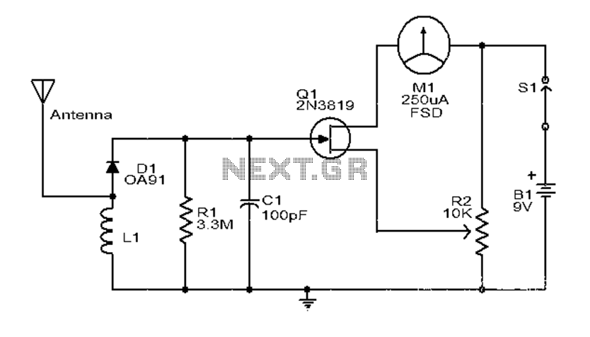
This is a simple and low-cost broadband high-frequency electric field strength meter. The field strength of the radio signal is converted into a DC measurement for analysis. The signal is captured by a coil and processed through a diode...
This circuit generates a two-tone effect similar to the cuckoo song. It can be utilized for doorbells or other applications due to its integrated audio amplifier and loudspeaker. As a sound effect generator, it can connect to external amplifiers,...