
VHF UHF HF active antenna electronic circuit project with explanation

The active antenna circuit described is designed to enhance signal reception across various radio frequency bands, making it versatile for different applications. The MFE201 dual-gate MOSFET serves as a key component in achieving high gain and low noise performance, which is essential for effective RF amplification. The use of the 2SC2570 NPN transistor complements the MOSFET by providing additional amplification for the VHF range, ensuring that weak signals can be boosted for better clarity and reception.
The implementation of dual DPDT switches allows for user-friendly operation, enabling the selection between the HF and VHF/UHF pre-amplifiers depending on the user's needs. This feature is particularly advantageous for users who may want to switch bands without the need for additional circuitry or manual adjustments. Furthermore, the ability to bypass the amplification stage by turning off the circuit through switch S2 allows for direct RF signal coupling, which can be beneficial in scenarios where amplification is not required or when testing the receiver's performance with a direct signal.
Powering the circuit with a 9-volt DC supply ensures that it remains compact and portable, making it suitable for indoor use where space may be limited. The design's simplicity not only makes it accessible for hobbyists and electronics enthusiasts but also allows for easy troubleshooting and modifications. Overall, this active antenna project exemplifies an effective solution for enhancing RF signal reception across multiple frequency bands while maintaining ease of use and practicality.A very simple and efficiency active antenna electronic project can be designed using this electronic schematic circuit that is based on transistors. This active antenna electronic project is useful for a wide range of RF frequencies covering three RF bands HF, VHF and UHF.
This simple active antenna is designed to amplify signals from 3 to 3000 MegaHertz, including three recognized ranges: 3-30Mhz high-frequency (HF) signals; 3-300Mhz veryhigh frequency (VHF) signals; 300-3000MHz ultra-high (UHF) frequency signals. MFE201 N-Channel dual-gate MOSFET) and Q2 (which is an 2SC2570 NPN VHF silicon transistor). Those transistors provide the basis of two independent, switchable RF pre-amplifiers. Two DPDT switches play a major role in this circuit, switch S1 used to select one of the two pre-amplifier circuits (either HF or VHF/UHF) and switch 2 is used to turn off the power to the circuit, while coupling the incoming RF directly to the input of the receiver.
This circuit must be powered from a simple 9 volt DC power circuit ( or a 9 volts battery) and is very useful for use as an indoor antenna 🔗 External reference
Related Circuits
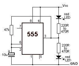
This LED flasher circuit utilizes the 555 timer integrated circuit (IC). The circuit diagram is straightforward and requires only a few external components. When operational, the red LEDs will flash sequentially at a predetermined frequency, similar to the indicators...
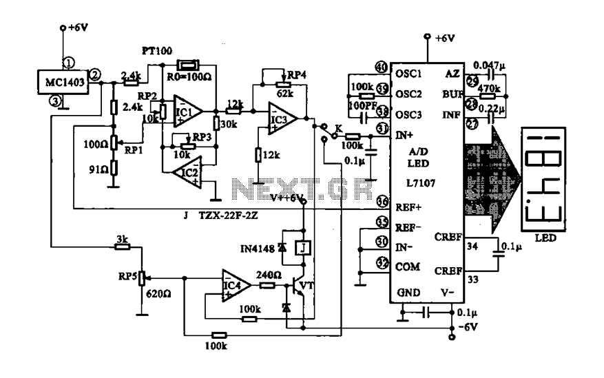
The digital display temperature detection circuit utilizes a precision digital display to indicate temperature readings. The circuit employs the MC1403, which outputs a reference voltage, with the potentiometer RP5 setting the reference value for the inverting terminal (a) of...
This circuit demonstrates a dynamic AC signal level display drive, which can be utilized for audio level display purposes. The AC signal detection and drive control are achieved using the BA6124 integrated circuit, along with five external colored light-emitting...
The core component of this circuit is the 555 timer IC. The alert sound does not stop immediately when the switch is activated; instead, it ceases automatically after a predetermined time period, which is set by the resistance of...
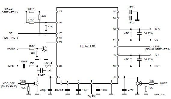
The pilot detector output is configured as an open collector output, requiring an external pull-up resistor. To set the decoder to "MONO," Pin 19 must be clamped to a voltage below 0.8V. The open collector output configuration allows for multiple...
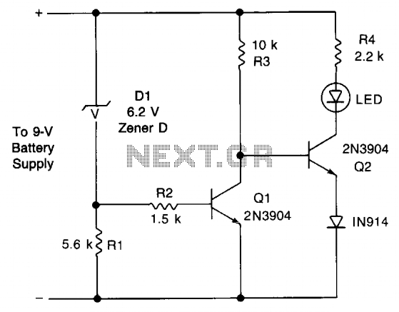
This circuit provides an early warning for battery discharge. A Zener diode (D1) is selected to indicate when the voltage falls below 9 V. If the supply voltage drops below 7 V, D1 will stop conducting, which will cause...