
Voltage monitor circuit

The described circuit employs a Zener diode (D1) to create a voltage reference point at 9 V. This component is critical in monitoring the voltage level of the battery. When the battery voltage is above 9 V, D1 remains in a conducting state, allowing current to flow through Q1, keeping it in the 'on' state. This action ensures that the output remains stable and does not trigger any warning signals.
As the battery discharges and the voltage drops to 7 V, D1 will no longer conduct. This cessation of current flow causes Q1 to turn off, which results in an increase in the collector voltage of Q1. The increased voltage at the collector will forward-bias Q2, allowing it to conduct. This conduction of Q2 activates LED1, providing a visual indication that the battery voltage has fallen below the critical threshold.
Resistor R4 is incorporated in series with LED1 to limit the current flowing through the LED, thereby protecting it from excessive current which could lead to failure. The choice of resistor value is essential to ensure that LED1 operates within its specified current range.
This circuit is particularly useful in battery-operated devices where monitoring battery health is crucial for reliable operation. By providing an early warning signal, it allows users to take action before the battery voltage drops to a level that could lead to device malfunction or damage.This circuit gives an early warning of the discharge of batteries. Zener diode Dl is chosen for the voltage below which an indication is required (9 V). Should the supply drop to below 7 V, Dl will cease conducting causing Ql to shut off. Its collector voltage will now increase causing Q2 to start conducting via LED1 and its limiting resistor R4.
Related Circuits
The gain of the single-stage virtual earth amplifier IC1 is determined by the drain-source resistance of the field-effect transistor (FET). Resistors R1, R2, and R3 linearize the FET's voltage-current characteristic. A control voltage is derived from the output signal...
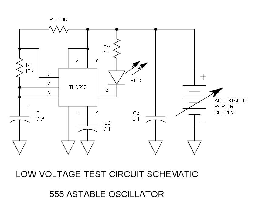
There have been stories regarding the suboptimal performance of the 555 timer IC when operated below a supply voltage (Vcc) of 5V, prompting an investigation into potential improvements for its operation. The 555 timer IC is a versatile device commonly...
Any step-down DC-DC converter can be utilized as an inverter without modifications to the operating schematic. The only differences between the standard step-down application and the inverting operation are the labels of the connection points. The step-down VOUT is... A...
The FM telephone circuit is constructed on a compact PC board that can be easily integrated into the housing of a telephone, functioning as a pseudo-speak earphone. This FM circuit connects in series with the telephone line, drawing power...
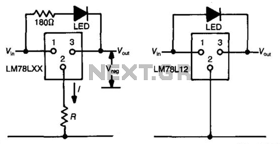
The three-terminal regulator device (LM78LXX) provides an output voltage (Vout) equal to the input voltage (Vm) until the input voltage exceeds the output voltage by 1.5 to 2 volts. A regulated voltage (Vreg) is achieved at this point, with...
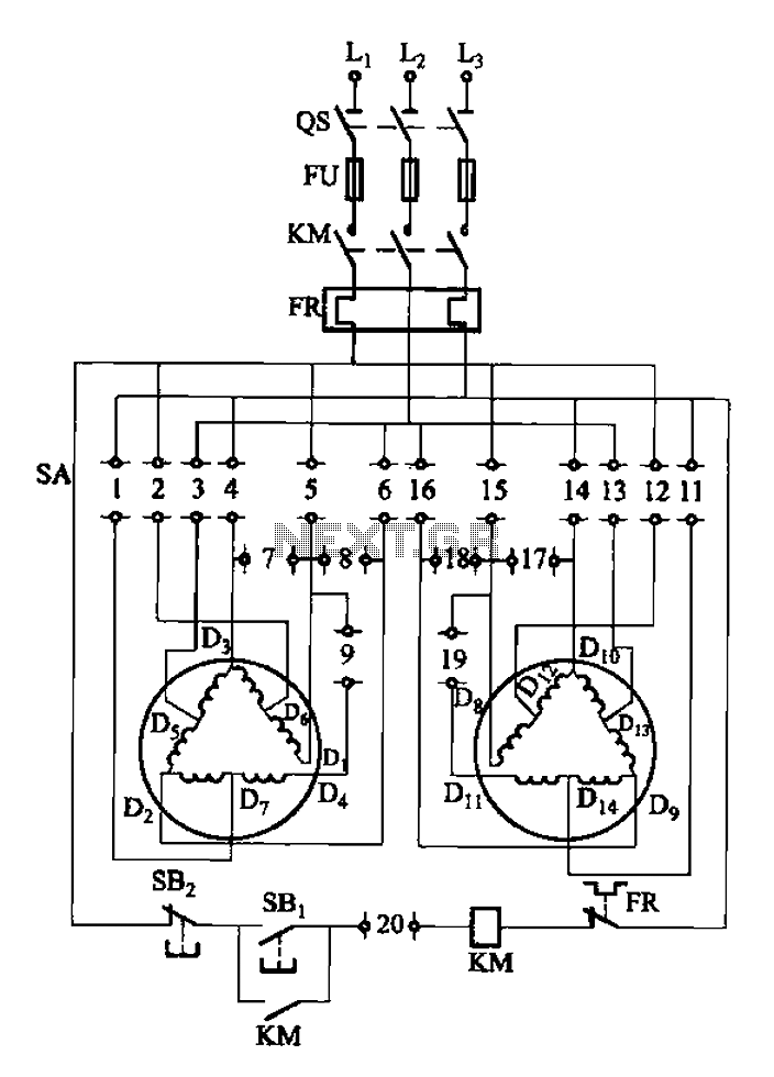
The 3-119 circuit shown in the figure combines switch SA to realize the stator windings, specifically the 2, Y, and 2Y connections, which correspond to the motor speed n1. The 3-119 circuit is designed to facilitate the control of motor...