
schematic computer multiplier sequence
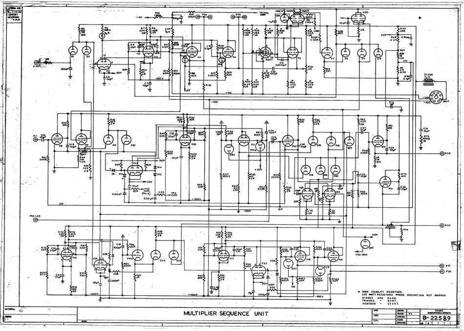
The schematic diagram of CSIRAC serves as a crucial reference for understanding the architecture and functionality of this pioneering computer. It provides a visual representation of the circuit, detailing how various components such as vacuum tubes, resistors, capacitors, and other elements are interconnected. Vacuum tubes, which function as electronic switches or amplifiers, were fundamental to the operation of CSIRAC, allowing for signal modulation and control.
Capacitors in the circuit played a vital role in energy storage and signal smoothing, contributing to the overall stability and performance of the computer. The schematic not only aids in the construction of the circuit but also facilitates troubleshooting and maintenance, enabling engineers to identify and rectify issues that may arise during operation.
Furthermore, the detailed connections illustrated in the schematic are essential for understanding the flow of electrical signals within the system. Each line and symbol represents specific electrical pathways and component functions, ensuring that the circuit operates as intended. This document is invaluable for both historical reference and educational purposes, providing insight into the early development of computing technology.Schematic diagram in hard copy relating to the computer CSIRAC. A schematic diagram shows the detailed connections between all the components in a circuit. Such diagrams were used to build circuits and later for testing. For CSIRAC, the most common components were vacuum tubes (valves), capacitors a.. 🔗 External reference
Related Circuits
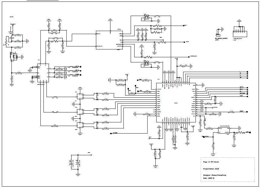
Analog baseband digital circuit table of contents: EMI interface, BPI bus, JTAG, LCD interface, keypad, UART, MINT, GPIO, MCP keypad, audio, RF, I/O connector, power cones, serial time, battery charging and analog, LED driver, RF control, JTAG, IOTA, audio...
The Boss SD-1 Super OverDrive is a pedal characterized by a straightforward design, incorporating a dual operational amplifier (uPC4558C) and six transistors, along with an asymmetric overdrive circuitry that emulates the classic, natural growl of a tube amplifier. It...
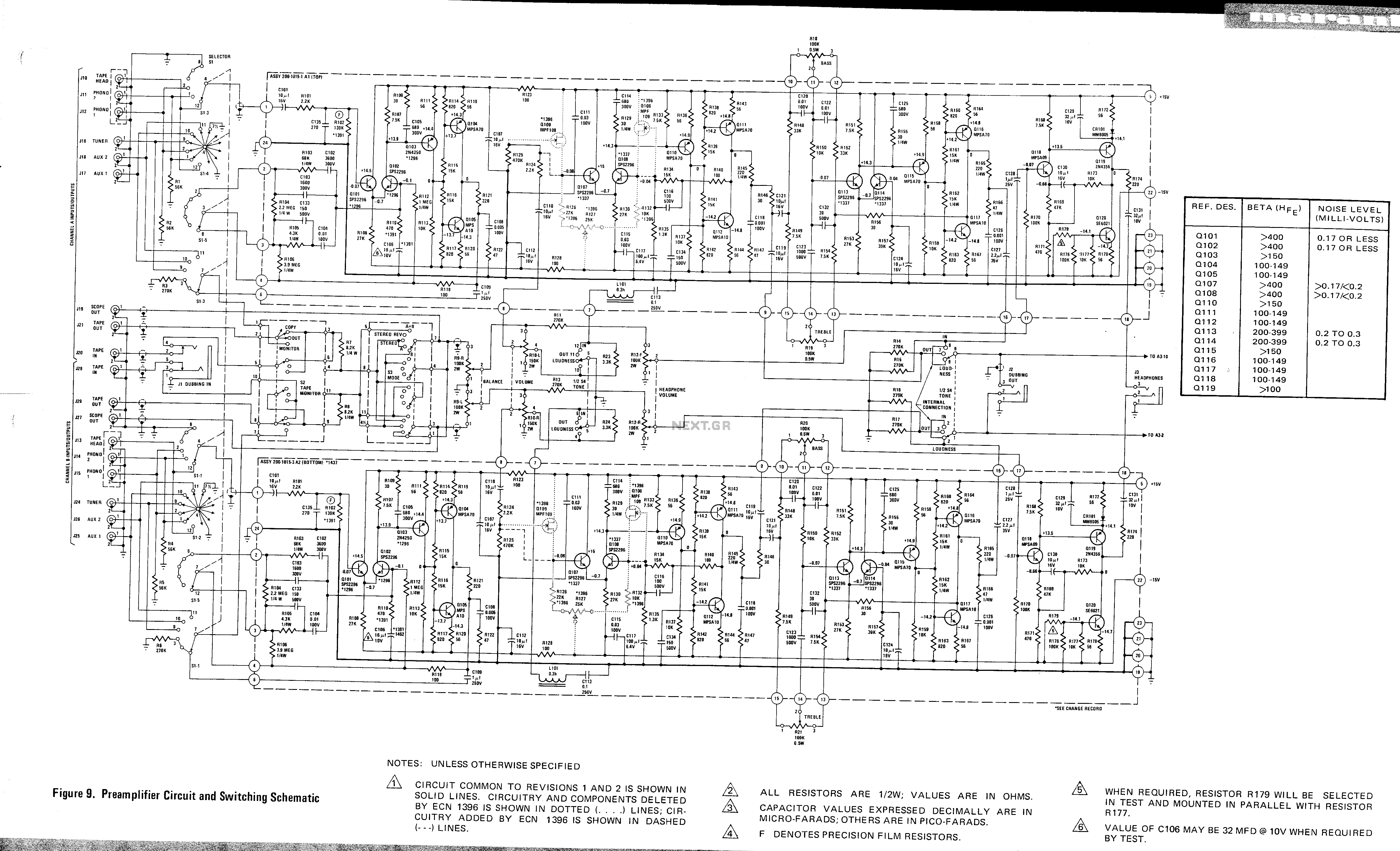
This is a preamplifier circuit and switching schematic for the Marantz Model 33. The Marantz Model 33 preamplifier circuit is designed to amplify low-level audio signals from various sources before sending them to a power amplifier. The schematic typically includes...
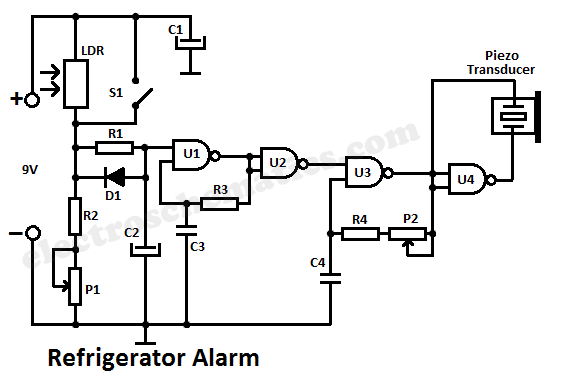
A simple light fence security beeper is presented. This circuit can function as a door alarm, gate alarm, pathway alarm, etc. It can be powered by any 12 Volt DC power supply. The operation of this circuit is straightforward....

The third Eagle layout of the program counter has been completed, presenting a clearer design compared to the previous iterations, which were cluttered with intersecting wires, making it difficult to discern connections. This diagram is intended to facilitate understanding...
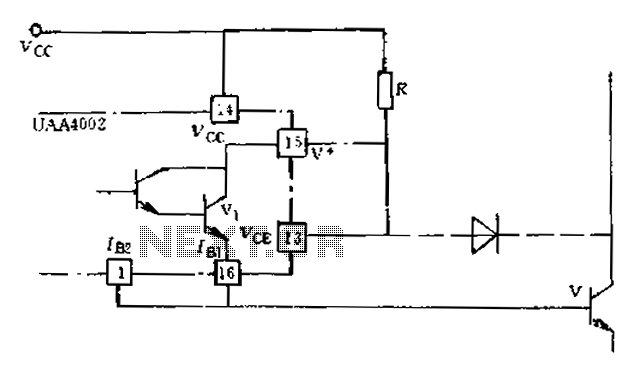
Anti-saturation devices have been removed from the UAA4002 routine applications. The base current of the switching transistor, which is driven by another transistor, is automatically adjusted. This adjustment allows the power transistors to operate in critical saturation. However, when...