
Video Distribution Amplifier

The circuit design of the video distribution amplifier is essential for maintaining signal integrity over multiple outputs. The choice of the IC 733 as the main amplification component is significant due to its ability to handle video frequencies effectively while providing adequate gain. The inclusion of adjustable amplification via VR1 allows for fine-tuning based on specific cable lengths and load conditions, which is critical in real-world applications where varying impedance can impact performance.
The filter circuit, composed of two parallel capacitors, is crucial for eliminating high-frequency noise that could interfere with the video signal. This ensures that only the desired frequency range is amplified and distributed. The buffer stage, constructed with transistors T1 and T2, enhances the output drive capability, allowing the amplifier to maintain signal fidelity even when driving multiple loads. The heat sinks attached to the transistors are necessary to dissipate heat generated during operation, especially under maximum load conditions.
The power supply section is designed for simplicity and reliability. The transformer X1 not only steps down the voltage but also provides isolation from the mains supply, enhancing safety. The bridge rectifier efficiently converts AC to DC, while the filtering capacitors smooth out the rectified output, ensuring stable voltage levels. The use of dedicated voltage regulators (7805 and 7905) ensures that the amplifier operates within specified voltage ranges, providing consistent performance across all components of the circuit. This careful design consideration contributes to the overall robustness and effectiveness of the video distribution amplifier in various applications.During the distribution of the video some losses and distortion might occur to decrease the quality of the video, but don`t worry here is a simple electronics project to overcome the problem, This video distribution amplifier enables four video recorder or TVs to be connected to the output of one VCR or VCP. The circuit Video Distribution Amplif ier can be used as distribution amplifier not only for VCR or VCP but also for all other signal having a bandwidth of about 10 MHz. The circuit of video distribution amplifier utilizes popular IC 733 (IC1) which is a simple single-chip amplifier.
This IC can be used to amplify the signal with a bandwidth up to 20 MHz. Here in this circuit, it is used only for up to 10 MHz because video bandwidth is about 5 MHz max. The gain provided by this IC is five times which should be more than sufficient to compensate for cable losses and loading losses. The input video signal is given to the video distribution circuit through filter circuit made from two parallel capacitors as shown in circuit diagram.
Variable resistor VR1 allows to set the amplification to some extent and given to the input of IC1. The output of IC1 from pin 7 is given to buffer amplifier made from transistor T1 and T2. Transistor T2 serves as a current source for T1. The heat sinks are used for both transistor T1 and T2 because their working current is set to 100 mA. The resistor networks at the output serve as impedance matching networks if long coaxial cables are used.
The power supply for the system is very straightforward and simple. The mains AC supply is stepped down by transformer X1. The output of the secondary transformer is rectified by a bridge rectifier comprising diodes D3 through D6 and filtered by capacitors C21 and C22. The regulated +5V and -5V from regulators 7805 (IC2) and 7905 (IC3) powers the entire circuit. 🔗 External reference
Related Circuits
High Quality simple design No need for a preamplifier Can be directly connected to CD players, tuners and tape recorders. Simply add a 10K Log potentiometer (dual gang for stereo) and a switch to cope with the various sources...
Feedback in a public address amplifier should be avoided. The ideal solution is to adjust the positions of the microphone and speaker; however, this is not always feasible in many situations. A frequency shifter that alters the output frequency...
The objective of this design is to create a Combo amplifier that is reminiscent of those commonly found in the 1960s and 1970s. It is particularly effective as a guitar amplifier but is also suitable for various electronic musical...
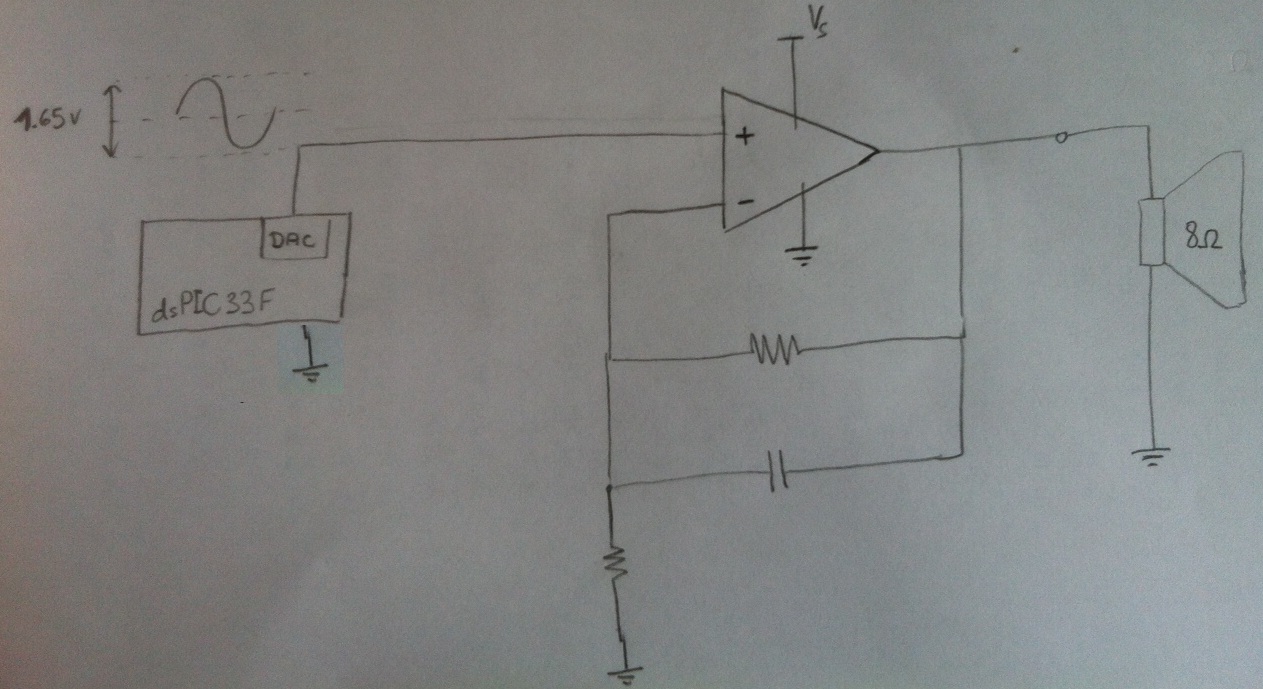
Design a circuit in which a microcontroller produces a signal and then uses an amplifier to drive an 8-ohm speaker. The LM386 has been used previously, but it cannot exceed 1W, which is insufficient. Additionally, a second-order anti-aliasing low-pass...
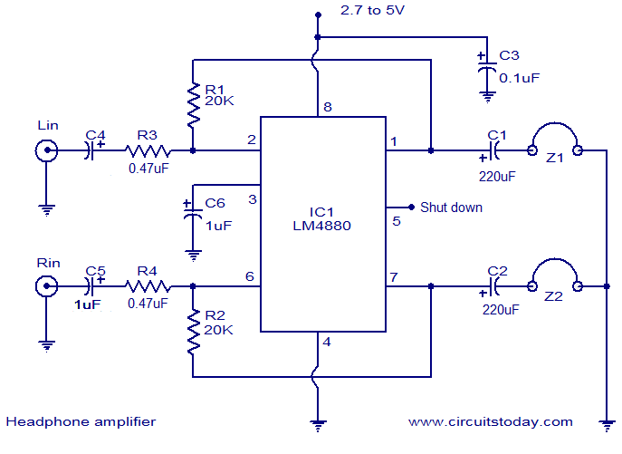
The LM4880 is a high-fidelity dual audio amplifier integrated circuit (IC) from National Semiconductors. This IC is specifically designed to deliver high-quality audio output with a minimal number of external components. The LM4880 can provide 250mW per channel into...
The following segment provides the enhanced Motorola schematic for a typical application of the MRF141G, which includes parasitic stabilization features. The MRF141G is a broadband power RF MOSFET capable of delivering a conservatively rated 300 watts across the FM...