
Video Line Selector

The video line selector circuit is designed to facilitate the analysis of specific scan lines within a video signal by generating trigger pulses that synchronize with the desired line. The core components typically include a microcontroller or a dedicated timing circuit, which processes the input video signal and identifies the timing of each line.
The circuit operates by receiving a composite video signal, which contains both the video information and synchronization pulses. The microcontroller analyzes the horizontal sync pulses to determine the start of each scan line. Once a specific line is selected, the microcontroller generates a precise trigger pulse that is output to the oscilloscope.
The key features of the video line selector include adjustable line selection, which allows the user to specify any line within the video frame, and a simple user interface, often comprising a rotary switch or push buttons. The output trigger pulse is typically TTL-compatible, ensuring compatibility with most oscilloscopes.
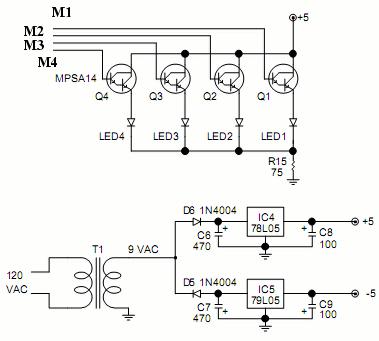
To enhance functionality, the circuit may also incorporate indicators such as LEDs to show the current line selection status. Power supply considerations for the circuit usually involve a low-voltage DC supply, ensuring safe operation and minimizing interference with the video signal.
Overall, the video line selector serves as a valuable tool for engineers and technicians who require precise visualization of individual lines in video signals for troubleshooting, analysis, or educational purposes.When measure video signal with oscilloscope, video line selector is very useful to find a scan line. The line selecter generates trigger pulse at selected line, oscilloscope will display only selected line. This is a very simple video line selector. 🔗 External reference
Related Circuits
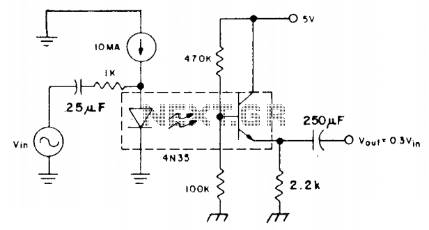
The coupler is biased in the linear region using a 10 mA DC bias on the infrared emitting diode (IRED) and a voltage divider connected to the base of the phototransistor. This configuration allows the photodiode current to flow...
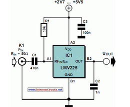
The National Semiconductor LMV225 is a linear RF power meter integrated circuit (IC) in a surface-mount device (SMD) package. It operates over a frequency range of 450 MHz to 2000 MHz. The LMV225 is designed for precise measurement of radio...
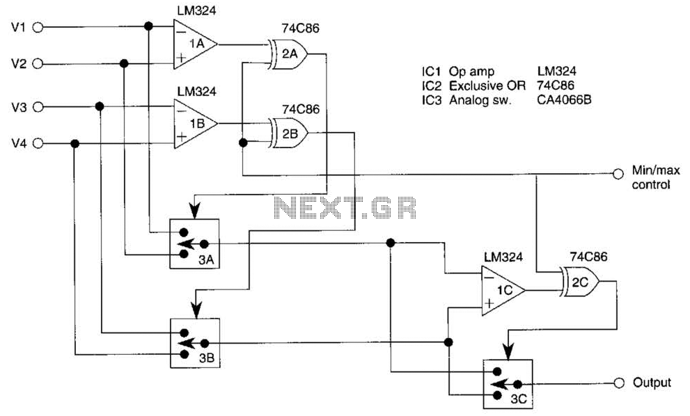
This circuit outputs the maximum or minimum of four input voltages, V1, V2, V3, and V4. Each of these input voltages ranges from 0 to 5 V. The output of the circuit is the maximum of V1, V2, V3,...
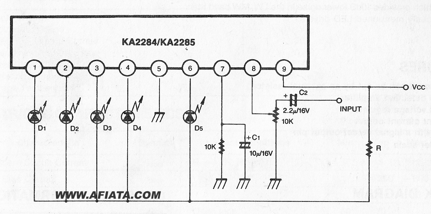
The KA2284 is a monolithic integrated circuit designed for 5-dot LED level meter drives with a built-in rectifying amplifier. It is suitable for both AC and DC level meters, such as VU meters or signal meters. The KA2284 integrated circuit...
The light sources for mirror screws consist of a dozen or more high-brightness LEDs, available in various colors or white, typically connected in parallel or series-parallel configurations. Two amplifiers are shown, capable of handling the full range of video...
A video switcher circuit is required to display multiple sources on a single monitor. The circuit schematic below features the MAX454, which serves as the core component of this video switcher. The MAX454 is a video multiplexer-amplifier manufactured by...