
Four-Input Minimum Maximum Selector Circuit

This circuit operates as a voltage selector, utilizing a combination of comparators and multiplexers to determine either the maximum or minimum value among the provided inputs. The four input voltages, V1 through V4, are fed into a series of operational amplifiers configured as comparators. These comparators compare the input voltages against each other and produce a binary output indicating which voltage is higher or lower based on the control voltage.
When the control voltage is set to 5 V, the circuit prioritizes finding the maximum voltage. This is achieved through the use of a priority encoder, which selects the highest voltage from the inputs. The output is then sent to a buffer to ensure that the signal can drive subsequent stages without degradation.
In the case where the control voltage is 0 V, the circuit switches its function to find the minimum voltage. This is accomplished by inverting the logic of the comparators or by using additional circuitry to ensure that the lowest voltage is selected and outputted.
The cascading capability of the circuit allows for the extension of its functionality. By connecting multiple units, it becomes feasible to handle a larger number of input voltages, adhering to the formula of 3N + 1, where N is the number of cascaded units. This modular approach enables flexibility in design, accommodating various applications where maximum or minimum voltage selection is critical, such as in analog signal processing, sensor data handling, or automated control systems.
In practical implementations, careful consideration must be given to the power supply, grounding, and layout of the circuit to minimize noise and ensure stability. Additionally, the selection of components such as operational amplifiers and multiplexers should be done based on their specifications to maintain performance across the desired voltage range. This circuit outputs the maximum (or the minimum) of the four input voltages Vv V2, V3, and V4. Each of these input voltages is in the range 0 to 5 V. The output of the unit is the maximum of Vv V2, V3, and V4 if the control voltage input is 5 V (i.e., logical 1). The output is the minimum of Vv V2, V3, and V4 if the control input is zero. By cascading TV such units, one can select the maximum (or the minimum) of 3N + 1 input voltages. Thus if k is the number of input voltages, we need [(/c+l)/3] units.
Related Circuits
This circuit triggers an alarm when its LDR (Light Dependent Resistor) sensor is exposed to light from the sun or a lamp. A 555 astable multivibrator is utilized to generate a tone of approximately 1 kHz upon detecting light....
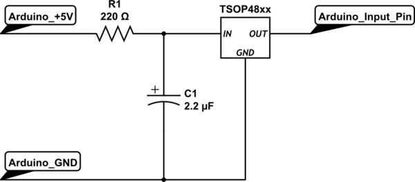
To set up the circuit, a resistor is required; a value of 200 Ohms is suggested, with a supply voltage of 3.3V. The resistor should be connected to the power line and grounded. The data line must be connected...
The ML7005 is a multi-functional DTMF transceiver LSI that incorporates a DTMF signal generator, a DTMF signal receiver, a call progress tone generator, a call progress tone detector, and a FAX (FX) signal detector. Each functional block can be...
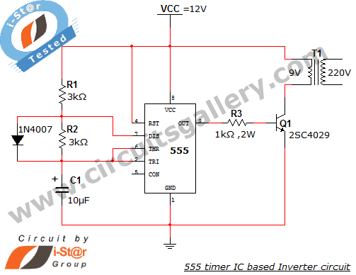
This article explains what an inverter is and how to construct a simple, low-cost 12V to 220V inverter circuit. An inverter functions as a DC to AC converter and is a valuable electronic product for compensating for emergency power...
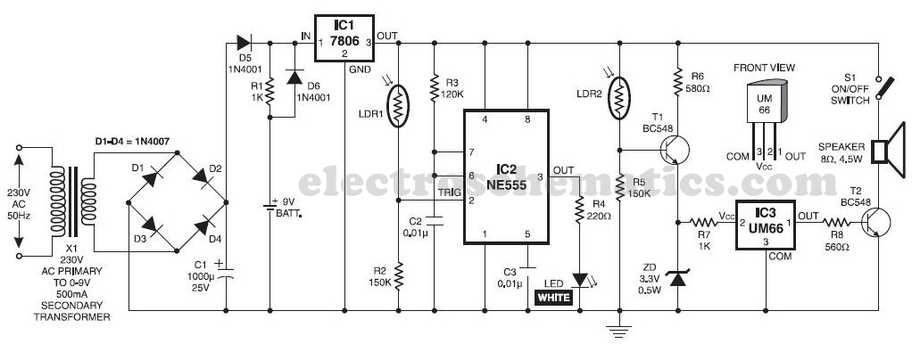
This musical light alarm circuit is very simple and uses only seven components, including a light-dependent resistor (LDR) and a 3.6V battery or three 1.2V rechargeable batteries. The well-known UM66 is utilized as the sound generator, providing a pleasant...
This is a solar tracking circuit designed to harness power from sunlight. The circuit operates optimally by maximizing sunlight exposure to generate electricity. The solar tracking circuit utilizes a combination of photovoltaic (PV) cells, sensors, and a microcontroller to adjust...