
Video Power Amplifier

The video power amplifier circuit is designed to enhance the quality of video signals in applications where audio and video are transmitted independently. This configuration is particularly beneficial in environments that require high fidelity video output without interference from audio signals. The circuit typically includes a series of transistors or operational amplifiers configured to boost the video signal amplitude, thereby improving the overall performance of video transmission.
In the schematic, the input section is connected to the video source, which can be a camera or other video-generating device. The video signal is fed into the amplifier stage, where it is processed to increase its voltage level. Components such as resistors and capacitors are strategically placed to stabilize the signal and filter out any unwanted noise that may affect video quality.
It is crucial to ensure that the audio and video paths are kept separate to prevent crosstalk and maintain signal integrity. The audio connection should be routed independently to avoid interference with the video signal processing. This separation is particularly important when using AV compounds, as it allows the circuit to function optimally without degrading the quality of either signal type.
The output of the video amplifier connects to the display or recording device, ensuring that the enhanced video signal is delivered with minimal distortion. The circuit may also include feedback mechanisms to further refine the amplification process, ensuring consistent performance across various operating conditions.
Overall, this video power amplifier circuit is an essential component for systems requiring high-quality video transmission, particularly in setups that utilize separate audio and video signal pathways. Proper implementation of this circuit will result in improved video clarity and reliability, making it suitable for a range of applications from home theater systems to professional video production environments.Video Power amplifier circuit diagram. The scheme works only when using the compounds of AV where video and audio signals are sent separately. Not suitable for joints «HF » antenna cable. Make sure to include the video amplifier in the line of the video, while leaving the audio connection.
🔗 External reference
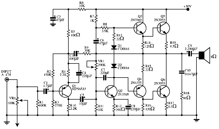
Related Circuits

The signal can be converted by piezoelectric films in various ways, including thermal to electrical (temperature sensor) and mechanical to electrical (microphone). Piezoelectric films are materials that generate an electrical charge in response to applied mechanical stress or temperature changes....
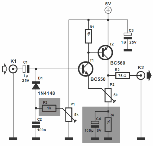
The video amplifier illustrated in the diagram represents a well-established design that is simple yet highly effective. However, there is a risk of damaging the transistors if the potentiometers, which control black level and signal amplitude, are set to...
More: The input data lacks specific content, providing only placeholders without any detailed information. In the context of electronic schematics, a comprehensive description typically involves detailing the components, their interconnections, and the overall functionality of the circuit....
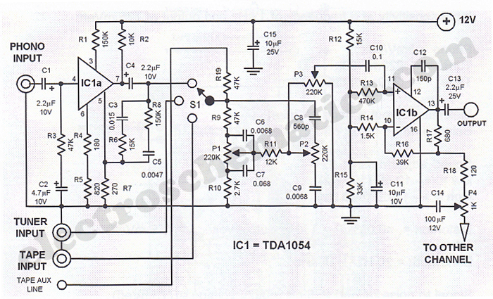
This Hi-Fi stereo preamplifier circuit is designed using the TDA1054 integrated circuit from SGS. The TDA1054 is a 16-pin DIL package that incorporates two separate preamplifier circuits. It is a low-noise preamplifier with minimal complications in the design process....
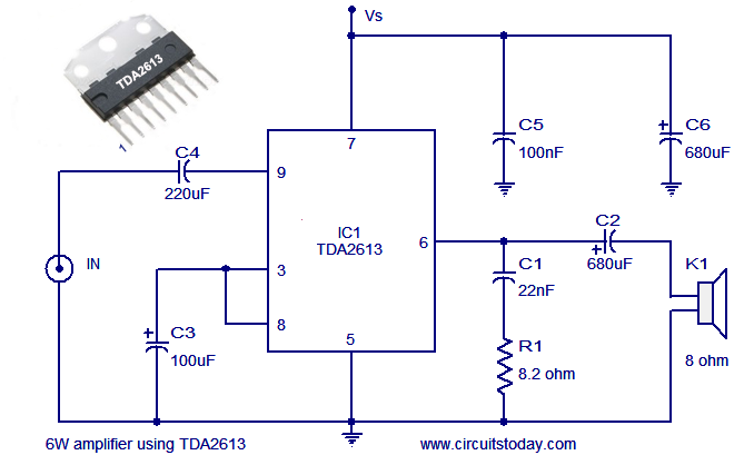
A simple and easy-to-build Hi-Fi audio power amplifier circuit is presented here. This 6-watt Hi-Fi audio amplifier circuit utilizes the TDA2613 integrated circuit (IC). The circuit design employs the TDA2613, which is a high-performance audio amplifier IC known for its efficiency...
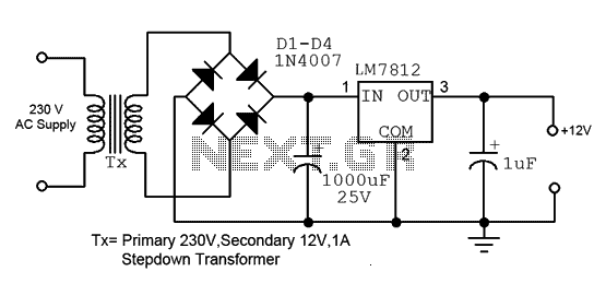
This is a straightforward 12V power supply circuit diagram. It features a fixed voltage output and is based on the LM7812 voltage regulator integrated circuit. The 12V power supply circuit utilizing the LM7812 voltage regulator is designed to provide a...