
Video Selector Circuit

The circuit operates as a channel selector, utilizing electronic switches to determine which of the two input channels is connected to the output. The logic signal controls the state of the switches, allowing for seamless transition between channels. When one channel is active, the other is shorted to ground, effectively eliminating any potential interference or crosstalk that could affect the quality of the signal.
The design ensures that the bandwidth of the circuit remains stable, with a -3 dB point at around 8 MHz, making it suitable for various applications that require signal integrity within this frequency range. The choice of components, including the switches and any associated passive elements, should be carefully considered to maintain performance specifications.
Buffering the circuit is crucial, particularly when interfacing with a 75-Ohm load. The switches may introduce insertion loss, which could degrade the signal if not adequately addressed. By incorporating a buffer stage, the circuit can provide the necessary drive strength and impedance matching, ensuring that the output signal remains robust and undistorted. This additional buffering stage can be implemented using an operational amplifier configured as a voltage follower or a dedicated buffer IC designed for high-frequency applications.
Overall, this circuit is effective for channel selection in communication systems, where maintaining signal quality and minimizing crosstalk are critical for optimal performance. This circuit selects one of two channels with a logic signal. The unused channel is shorted out, which minimizes crosstalk. The bandwidth at -3 dB is about 8 MHz. It is advisable to buffer this circuit because there is some loss in the switches when feeding a 75-Ohm load.
Related Circuits
Adding a discharge path to the upper MOSFET of a cascode circuit significantly reduces the unavoidable Miller effect, thereby enhancing the Power Factor Correction (PFC) performance of a power supply's front end. In a cascode configuration, the upper MOSFET is...
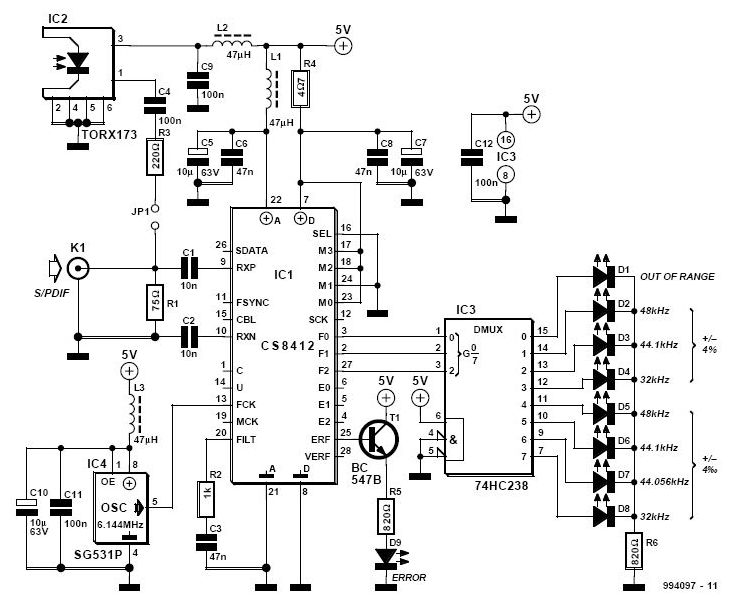
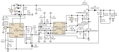
The S/PDIF monitor is an application of the digital audio interface receiver Type CS8412 from Crystal. Previous articles have covered the decoding of S/PDIF (Sony/Philips Digital Interface Format) into data, bit clock, and L/R clock for use in devices...
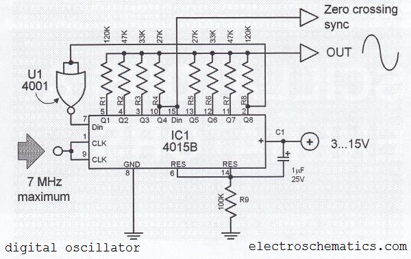
The digital sine wave generator (oscillator) circuit requires only a few components to produce signals with high amplitude constants and a wide range of variable frequencies. This circuit generates a sine wave signal, and by altering the values of...
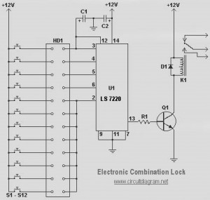
This circuit diagram represents a simple electronic combination lock utilizing the IC LS7220. The circuit is designed to activate a relay for controlling any device (on and off) each time a specific combination of four digits is entered. It...
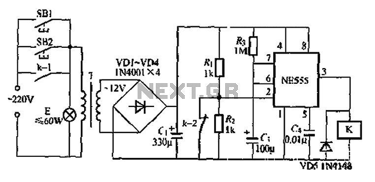
Another application involves the use of a NE555 delay lamp circuit, where components SB1 and SH2 act as J-light buttons that can be installed in two different locations. The lamp can be activated by pressing either SB1 or SB2,...
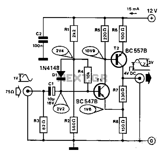
Commonly used for cameras or computers with black and white television connections, the amplifier has a gain of 3 and a bandwidth of 10 MHz. The described circuit is an amplifier designed for applications involving cameras or computers that interface...