
Visitor Counter Circuit using TSOP1736

The room light controller circuit integrates a microcontroller that processes inputs from a visitor counter. This setup is designed to automatically control the lighting based on the number of people present in the room. The primary components of the circuit include the microcontroller, sensors for detecting visitors, and a relay or transistor switch to control the light source.
The microcontroller is programmed to monitor the input from the visitor counter, which could be implemented using infrared sensors or ultrasonic sensors to detect movement. When a visitor enters the room, the sensor triggers an increment in the count, and the microcontroller processes this information to determine whether to turn the lights on or off.
For instance, if the count exceeds a predefined threshold, the microcontroller activates the relay, which in turn powers the lighting system. Conversely, when the count falls below this threshold, the microcontroller deactivates the relay, turning off the lights. This automated system not only enhances energy efficiency by ensuring lights are on only when needed but also improves user convenience by eliminating manual control.
Additional components may include an LCD display to show the current visitor count and status of the lights, as well as buttons for manual overrides. Power supply considerations are crucial, ensuring that the microcontroller and associated components receive stable voltage levels for reliable operation.
In summary, the room light controller using a microcontroller and visitor counter represents an efficient solution for smart lighting control, optimizing energy use while providing necessary illumination based on occupancy.This room light controller project automatically using Microcontroller Visitors Counter is a reliable circuit that takes the task of controlling the room. 🔗 External reference
Related Circuits
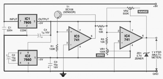
This DIY digital thermometer circuit can measure temperatures up to 150°C with an accuracy of ±1°C. The temperature is displayed on a 1V full scale deflection. The digital thermometer circuit is designed to provide accurate temperature readings within a specified...
In addition to its primary function as a headphone amplifier, this circuit is applicable in various scenarios requiring a wide bandwidth low power amplifier. It utilizes an operational amplifier (op-amp) with its output current enhanced by a pair of...
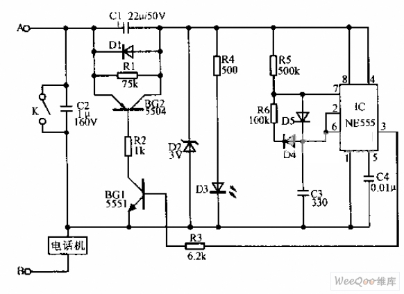
A simple telephone time lock circuit is depicted in the provided diagram. In this circuit, BG1 and BG2 function as electronic switches that are controlled by the IC NE555. When the telephone is on-hook, the DC resistance of the...
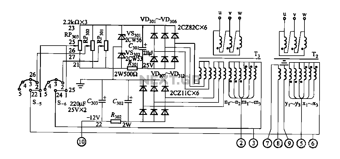
FGDF-3 is a three-phase low-temperature iron plating power supply circuit, while the KGDF-3 is a single-phase low-temperature iron plating power supply device that encompasses all the characteristics of the power supply unit. This design allows for an even distribution...
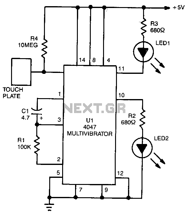
LED1 and LED2 indicators activate and stay illuminated each time the circuit is triggered. During the timing cycle, the Q output at pin 10 of U1 becomes positive when the Q output at pin 11 turns negative. The two...
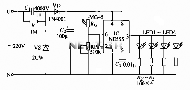
A 220V AC input is converted to a DC operating voltage of approximately 3.3V using a capacitive G buck regulator, a rectifier diode (VD), and a filter capacitor connected to an NE555 integrated circuit (IC). The IC functions as...