
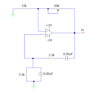
The basic circuit diagram of a differentiator

A basic differentiating circuit is designed to produce an output that is proportional to the rate of change of the input signal. In electronic applications, this is particularly useful for processing signals where rapid changes need to be detected, such as in waveform shaping or signal conditioning.
The circuit typically consists of a resistor (R) and a capacitor (C) arranged in a configuration that allows the differentiation of the input voltage (Vin). The output voltage (Vout) is derived across the resistor, and the relationship can be expressed mathematically as Vout = -RC(dVin/dt), where dVin/dt represents the derivative of the input voltage with respect to time. This indicates that the output voltage is inversely proportional to the rate of change of the input voltage.
In practical implementations, the values of R and C must be carefully selected to ensure that the circuit responds appropriately to the frequencies of interest. A high-pass filter characteristic is inherent in this differentiating circuit, allowing high-frequency signals to pass while attenuating low-frequency signals.
The circuit can be further enhanced by incorporating operational amplifiers (op-amps) to improve performance, increase gain, and provide better control over the output characteristics. By using an op-amp in a differentiating configuration, the circuit can achieve greater accuracy and stability, as well as the ability to handle a wider range of input signal amplitudes.
In summary, the basic differentiating circuit serves as a fundamental building block in various electronic applications, enabling the detection and amplification of rapid changes in input signals. As shown for the basic differentiating circuit. The differential operation circuit can input and output, the relationship between the output, between the input:
Related Circuits
An operational amplifier-based sine wave generator circuit, commonly known as a Wien bridge oscillator, is recognized for its simplicity and stability. The Wien bridge oscillator connects the Wien bridge circuit between the amplifier's input and output terminals. The bridge...
This type of sensor switch is ideal for creating touch-operated bells and buzzers in small toys, which function for a limited duration before automatically shutting off. The trigger's input impedance is very high, allowing the touch sensor switch to...
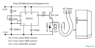
This is a simple freeze protector circuit diagram, also known as a timing circuit. It serves as a hobby project for beginners. This circuit can automatically operate any device after a fixed time once AC power supply is restored....
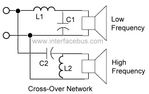
An audio crossover network is utilized within a speaker to separate or filter audio signals of varying frequencies to different speakers inside a speaker cabinet designed for those frequencies. This specific crossover network employs two passive components for each...
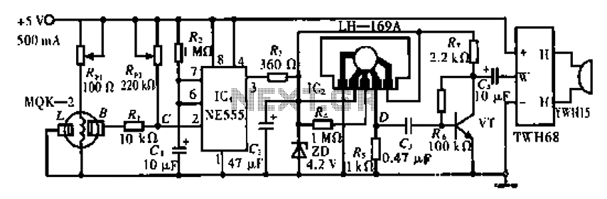
The circuit operates using the MQK-2 gas sensor, which detects the presence of combustible gases or smoke through surface adsorption. When gas is detected, the inter-electrode resistance (BL) decreases significantly. This change in resistance affects the voltage at node...
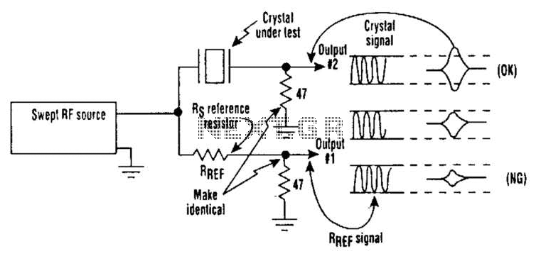
Occasionally, microprocessors and microcomputers may not be compatible with certain microprocessor crystals. Many data sheets for microprocessors specify maximum values for a crystal's equivalent series resistance (Rs), which may not be met by some crystals marketed for use with...