
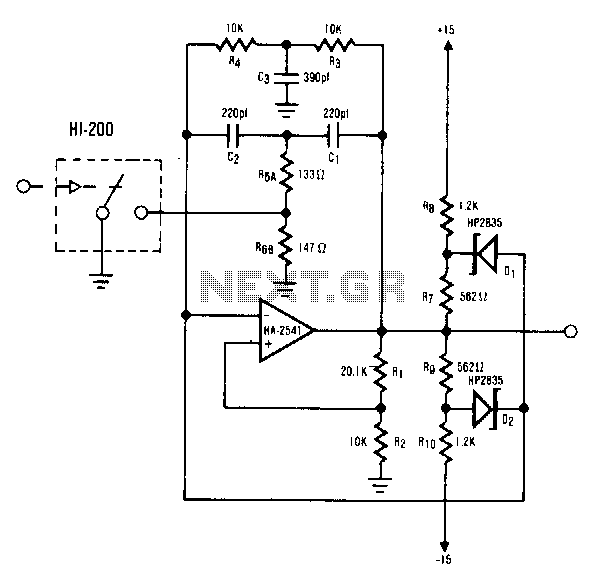
Voltage controlled amplifier

The operational amplifier circuit described operates as a differential amplifier, where the input signals are applied to the inverting (pin 2) and non-inverting (pin 3) terminals. The differential voltage of ±10 mV indicates that the circuit is designed for high precision, allowing it to amplify small voltage differences effectively. The additional input at pin 5 serves as a control mechanism, where the injected current (Iabc) modulates the gain of the amplifier. This feature is particularly useful in applications requiring dynamic adjustment of gain based on varying input conditions.
The output signal at pin 6 is a function of the differential input voltage and the gain set by the current at pin 5. This relationship can be expressed mathematically as V_out = Gain × V_diff, where V_diff is the voltage difference between pins 2 and 3. The linear control of gain ensures that the output signal remains proportional to the input, which is crucial for maintaining signal integrity, especially in audio applications.
Inserting an audio signal into this circuit allows for the amplification of audio frequencies, making it suitable for various applications such as audio processing, signal conditioning, and other electronic systems where precise signal amplification is required. The design ensures minimal distortion and high fidelity in the output, which is essential for high-quality audio performance.This circuit is basically an op amp with an nal (±10 mV) between pin 2 and 3 and by extra input at pin 5. A current Iabc is injected controlling the current on pin 5, the level of the into this input and this controls the gain of the signal output (pin 6) is controlled, device linerly
Thus by inserting an audio sig-.
Related Circuits
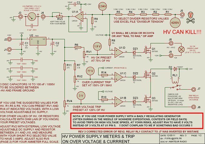
High voltage resistors for the high voltage divider are SFERNICE or PHILIPS type VR37 (3.5 kV - 0.4 W). They are not expensive (even if they are sold in quantities of 25 or 50 units), and it is always...
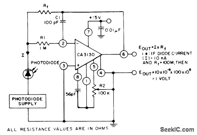
The circuit employs three CA3130 BiMOS operational amplifiers in an application that is sensitive to sub-picoampere input currents. It generates a ground-referenced output voltage that is proportional to the input current flowing through the photodiode. The described circuit utilizes three...
The microphone preamplifier circuit design presented in this schematic utilizes the SSM2015 component manufactured by Precision Monolithics Inc. (PMI). This component provides high amplification with low noise characteristics (1.3nV/f). The design is configured to handle differential input signals and...
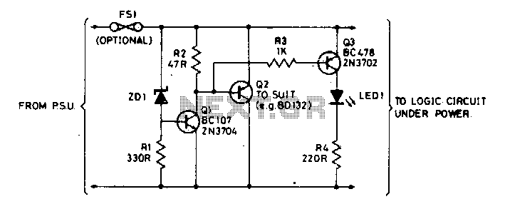
The Zener diode ZD1 monitors the supply voltage, and if the supply exceeds 6 V, transistor Q1 will activate. This activation causes transistor Q2 to conduct, thereby clamping the voltage rail. The subsequent behavior of the circuit is contingent...
The increase in industrial and computerized equipment that utilizes programmable memory has heightened the demand for reliable recording media. Currently, magnetic tape is one of the most prevalent methods. The essential element of any magnetic recording system is the...

A high-power and efficient 100W power amplifier electronic project can be designed using the STK404 audio power amplifier hybrid ICs. These ICs consist of optimally designed discrete component power amplifier circuits that have been miniaturized using SANYO's unique insulated...