
Voltage-To-Frequency Converter I
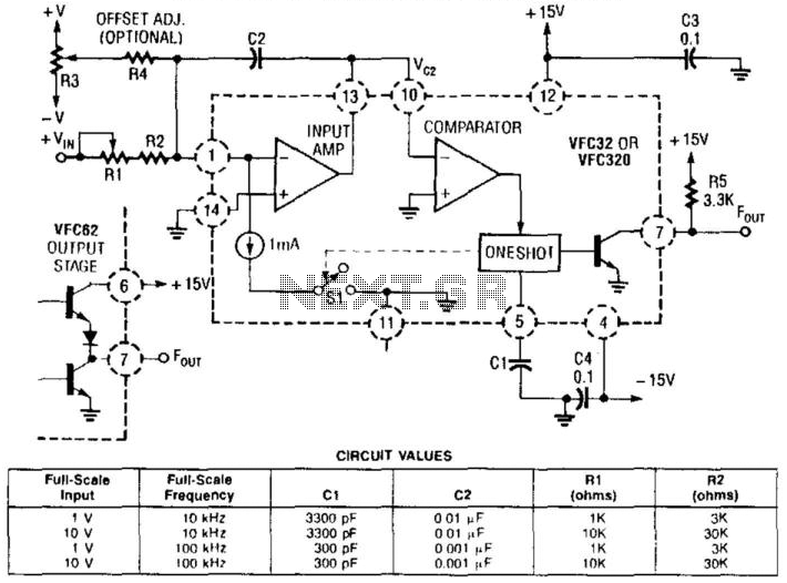
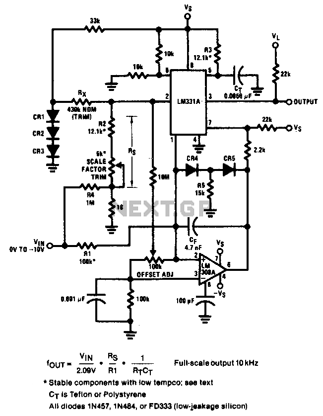
The voltage-to-frequency converter circuit based on the Burr-Brown VFC 32 IC is designed to convert an input voltage into a corresponding frequency output. This functionality is particularly useful in applications where analog signals need to be processed digitally. The circuit operates on the principle of charge balancing, which is essential for maintaining accuracy and stability in the conversion process.
The VFC 32 IC features a high level of integration, allowing for a compact design with fewer external components. The primary components include the VFC 32 IC itself, a resistor to set the output frequency range, and capacitors for stability and filtering purposes. The key parameter in this configuration is the 1-mA current source, which plays a crucial role in balancing the charge. By ensuring that the positive charge produced by this current source is equal to the negative charge from the input voltage, the circuit achieves reliable performance across varying input conditions.
The output of the V/F converter is a frequency signal that can be easily processed by digital systems, such as microcontrollers or digital signal processors. The waveforms produced by the V/F converter illustrate the relationship between the input voltage and the output frequency, providing a clear representation of the conversion process. This circuit is particularly advantageous in applications such as sensor interfacing, where it is necessary to convert varying analog signals into a format suitable for digital processing. Using a Burr-Brown VFC 32 IC, this voltage-to-frequency converter uses few components. The circuit values are shown in the figure. This charge-balanced V/F converter uses a VFC32 or a VFC320 IC. The positive charge from the 1-mA balances the negative charge from the input. V/F converter waveforms are shown in Fig. 100-l(b). 🔗 External reference
Related Circuits
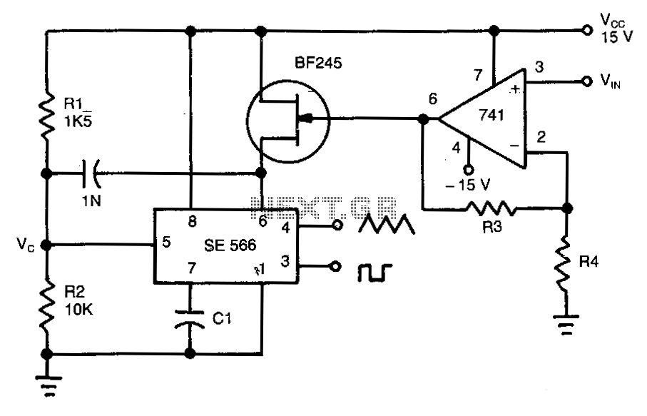
This circuit operates based on the frequency variation of the function generator in relation to the input voltage (ViN). The frequency is influenced by the capacitance and resistor connected to pin 6, with the resistor being substituted by a...
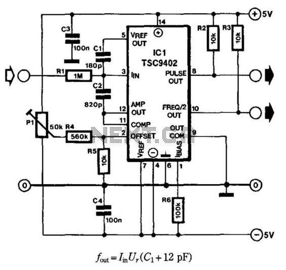
Teledyne Semiconductor's Type TSC9402 IC is highly suitable as an economical current-to-frequency converter. The maximum input current for the design depicted in the diagram is 10 mA (input voltage range is 10 mV to 10 V), while the output...
The Allegro ACS75x family of Current Sensors offers cost-effective and accurate solutions for current sensing in industrial, automotive, commercial, and communications systems. The device package facilitates easy implementation by the customer. Typical applications encompass motor control, load detection and...
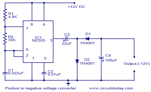
This circuit diagram illustrates the method for obtaining a negative voltage from a positive voltage supply. An additional benefit of this circuit is that the negative voltage, combined with the original positive supply, can be used to simulate a...
Below is the schematic diagram of an audio input module. This module is capable of producing a DC output voltage that is proportional to the amplitude of the input signal. The audio input module typically consists of several key components...
The circuit achieves an error of better than 0.02% and a nonlinearity of 0.003% within a ±20°C range around room temperature. The circuit's design focuses on precision and linearity, making it suitable for applications that require high accuracy in temperature...