
Voltage controlled variable gain amplifier

The tee attenuator is a crucial component in RF and audio applications where signal integrity and control are paramount. This passive device is designed to reduce the amplitude of a signal without distorting its waveform, thus maintaining the quality of the transmitted signal. The design typically consists of three ports: an input, an output, and a termination port, arranged in a "T" configuration.
The optimal dynamic linear range of up to 100 dB indicates that the attenuator can effectively manage signals over a wide range of amplitudes, making it suitable for various applications, including telecommunications, broadcasting, and instrumentation. The operational frequency of 10.7 MHz is significant, as it falls within the VHF range, commonly used in FM radio and other communication systems.
Proper layout is critical for the performance of the tee attenuator. Factors such as the placement of components, trace lengths, and grounding techniques can significantly affect the overall attenuation and frequency response. High-quality resistors with low temperature coefficients are typically employed to ensure stability and minimize variations due to environmental changes. Additionally, the use of appropriate PCB materials can reduce dielectric losses, further enhancing the performance of the attenuator.
In summary, the tee attenuator is an essential device for achieving precise signal management in various electronic applications, with specific attention required for layout and component selection to maximize its effectiveness at the specified operational frequency.The tee attenuator provides for optimum dynamic linear range attenuation up to 100 dB, even at f = 10 7 MHz with proper layout.
Related Circuits
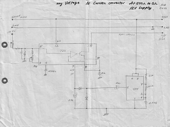
This circuit converts a voltage control output from a process controller into a current control signal, which is necessary when an AC drive or valve requires a current control signal. It operates as a three-wire voltage-to-current loop converter. A...
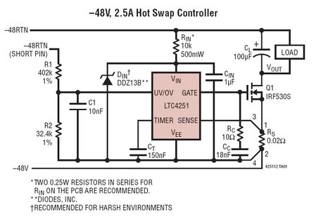
The LTC4251, LTC4251-1, and LTC4251-2 are negative voltage Hot Swap controllers designed to enable the safe insertion and removal of a board from a live backplane. The output current is managed through three stages of current limiting: a timed...
Given the variety of equipment in modern home entertainment systems, the ability to adjust the gain of both audio and video signals has become essential. This particular circuit has proven to be very useful when used alongside the General...
All miniature electronic devices operate off batteries. Some of them require higher than the standard battery voltages for efficient operation. If a battery with the specific voltage is unavailable, additional cells must be connected in series to increase the...
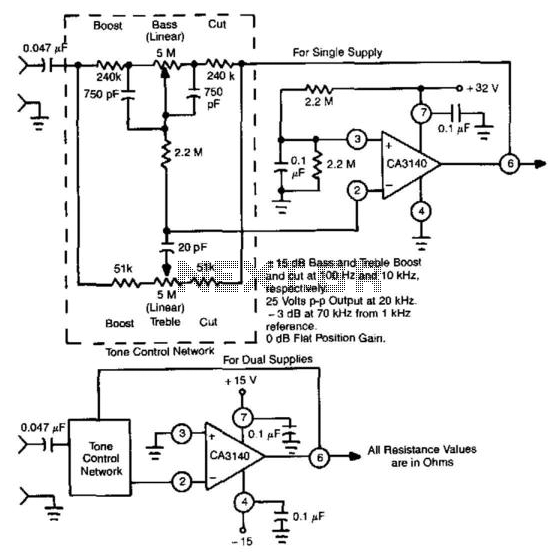
This circuit utilizes the high slew rate, high input impedance, and high output-voltage capability of the CA3140 BiMOS operational amplifier. It also offers mid-band unity gain using standard linear potentiometers. The circuit design leverages the characteristics of the CA3140 BiMOS...
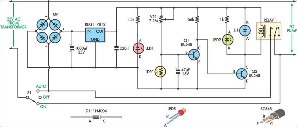
This circuit was designed to control a pump in a garden pond, enabling it to automatically activate at dawn and deactivate at dusk. The circuit utilizes a light-dependent resistor (LDR) to detect ambient light levels, which serves as the primary...