
Voltage controlled variable gain amplifier II

The 2N5457 is a junction field-effect transistor (JFET) commonly utilized in analog applications, particularly for its ability to provide variable resistance based on the applied gate-source voltage. Its maximum drain-source resistance (RdS) of 800 ohms allows it to effectively modulate signals in low-voltage applications.
In circuits where precise gain control is essential, the linearity of the 2N5457's resistance characteristics is advantageous. This linear behavior across a wide range of resistance values ensures that small changes in the gate voltage result in proportionate changes in output, making it suitable for applications such as audio processing, signal conditioning, and RF amplification.
When integrated with the LM101 operational amplifier, which operates effectively in low millivolt differential voltage conditions, the 2N5457 can enhance the overall performance of the circuit. The JFET's ability to maintain linearity across various operating points allows for smoother transitions in gain, reducing distortion and improving the fidelity of the amplified signal.
In summary, the combination of the 2N5457 JFET and the LM101 operational amplifier creates a robust platform for electronic gain control, leveraging the JFET's voltage-variable resistance characteristics to achieve high performance in low-voltage applications. This configuration is particularly beneficial in scenarios requiring precise signal manipulation and control.The 2N5457 acts as a voltage variable resistor with an RdS of 800 ohms max Since the differential voltage on the LM101 is in the low mV range, the 2N5457 JFET will have linear resistance over several decades of resistance providing an excellent electronic gain control.
Related Circuits
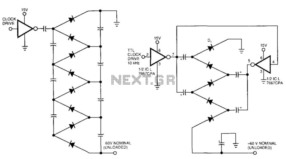
Figure 99-1(a)'s circuit exhibits a high output impedance due to the small effective capacitance of the series-connected capacitors, resulting in considerable voltage loss from the diode drops. This circuit requires two diodes and two capacitors to generate a DC...
The circuit in the diagram generates a negative voltage without using integrated circuits. It utilizes five n-p-n transistors driven by an approximately 1 kHz TTL clock. When the clock input is high, transistors T1 and T2 connect capacitor C1...
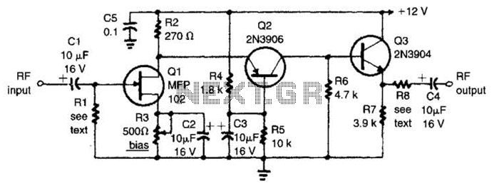
The circuit features a frequency response that spans from 100 Hz to 3 MHz, with a gain of approximately 30 dB. Field-effect transistor Q1 is arranged in a common-source self-biased configuration, and an optional resistor R1 is available to...
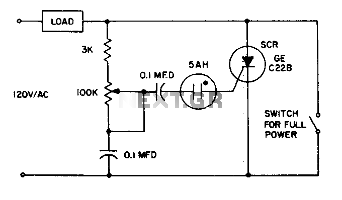
The 5AH will trigger when the voltage across the two 0 µF capacitors reaches the breakdown voltage of the lamp. Control can be obtained from full off to 95% of the half-wave RMS output voltage. Full power can be...
When the push button is pressed, a clock pulse appears on the CLK input of flip-flop IC1b. The output then toggles, causing the LEDs to turn off. Simultaneously, IC1a is reset, silencing the buzzer. Pressing the button again will...
For SR AB763 driver replace: 25k pot, 0.1uF cap and 4k7 resistor with 100 ohm resistor to ground. 56k resistor with 820 to 4k7 resistor. More: 6k8 resistor with 22k resistor. The circuit modification described involves specific component replacements and...