
XTR105 reverse voltage and over-voltage surge protection circuit

The XTR105 circuit is designed to protect sensitive electronic components from reverse voltage and over-voltage conditions that could lead to failure. The inclusion of a Zener diode, particularly one with a breakdown voltage of 36V, is critical in clamping excess voltage and preventing damage. The Zener diode can be selected from various models, such as the 1N4753A or the 1N6286A, both of which are suitable for this application.
In this configuration, it is important to ensure that the maximum supply voltage (Vps) does not exceed the minimum breakdown voltage of the Zener diode. This ensures that the Zener diode operates within its specified limits, providing effective protection to the circuit.
Furthermore, the diode bridge introduces a voltage drop of approximately 1.4V, which must be accounted for in the overall voltage supply calculations. This voltage loss affects the supply voltage available to the rest of the circuit, and therefore, the design must ensure that the remaining voltage is sufficient for proper operation of the XTR105 and any connected components.
Overall, careful selection of the Zener diode and thorough consideration of voltage drops in the circuit are essential for achieving reliable surge protection in applications utilizing the XTR105.Shown for the XTR105 reverse voltage and over-voltage surge protection circuit. Zener diode is 36V, or choose 1N4753A 1N6286A. Maximum Vps must be less than the minimum zener diode breakdown voltage of the diode bridge produce the loop supply voltage of 1.4V loss.
Related Circuits
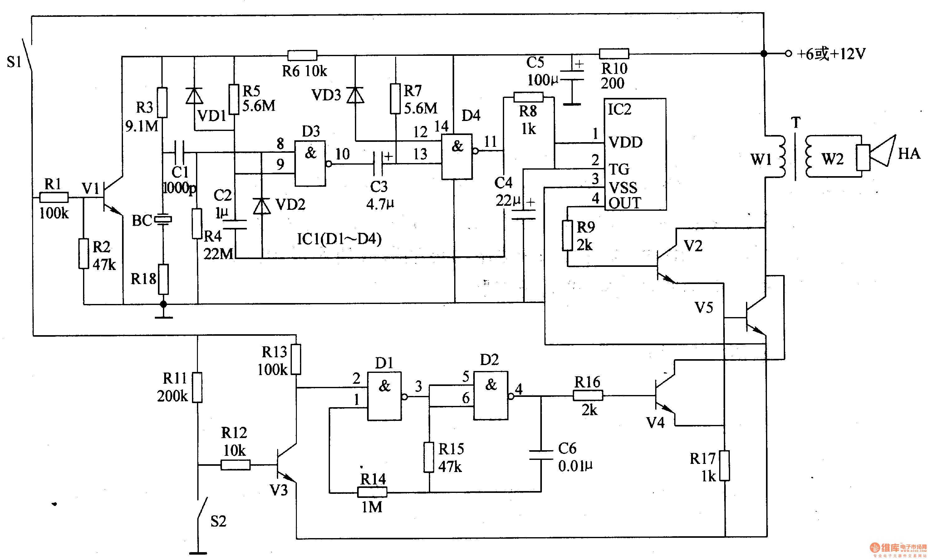
The motorcycle anti-theft alarm circuit consists of several components, including the anti-theft detection circuit, the control circuit, the sound generator, the audio oscillator, and the power amplifier output circuit, as illustrated in figure 7-91. The anti-theft detection circuit is...
The following circuit illustrates the TL084 integrated circuit (IC) used as a dynamo current voltage regulator, accompanied by a fuse box diagram. Features include a comprehensive control circuit that will... The TL084 is a quad operational amplifier that is commonly...

This is a 100-watt transistor inverter circuit diagram that features a straightforward design. The circuit utilizes only transistors, eliminating the need for integrated circuits. It converts a 12V battery input into a 220V output with a 50Hz square wave...

A delay circuit utilizing an operational amplifier functions as a comparator, providing high timing accuracy. The timer's delay range is from 1 to 30 seconds. The delay time is determined by resistors Ri, RP, and capacitor C. By adjusting...
This circuit generates dual-tone bell sounds similar to those found in standard doorbell units. It is applicable in various contexts beyond doorbells. The circuit, as depicted in the diagram, produces a "Ding-tone" when switch P1 is pressed and a...
A touch sensor relaxation oscillator is utilized in the hysteresis lab. In this schematic, the variable capacitor is represented by a person's finger and a touch plate made from aluminum foil and packing tape. Code was developed for the...