
Police Lights associate crystal rectifier Project
The circuit design incorporates a 555 timer IC, which is a versatile component commonly used in various timing applications. In astable mode, the 555 timer continuously oscillates between high and low states, producing a square wave output. The frequency of this oscillation is determined by the resistor and capacitor values connected to the timer. Typically, two resistors (R1 and R2) and a capacitor (C1) are used to set the timing parameters. The output frequency can be calculated using the formula:
\[ f = \frac{1.44}{(R1 + 2R2) \cdot C1} \]
The output from Pin 3 of the 555 timer is fed into the clock input of the CD4017 decade counter. The CD4017 is a popular decade counter that counts from 0 to 10 and provides ten output pins (Q0 to Q9). Each time a clock pulse is received, the counter increments its count by one, activating the corresponding output pin. This means that the first output pin (Q0) will turn on the first LED, the second output pin (Q1) will turn on the second LED, and so forth, creating a visual indication of the counting process.
The LEDs connected to the outputs of the 4017 will turn on and off in sequence as the counter increments. A current-limiting resistor should be used in series with each LED to prevent excessive current from damaging the LEDs. The choice of resistor value depends on the supply voltage and the forward voltage drop of the LEDs, calculated using Ohm's law.
This circuit can serve various applications, such as visual indicators, light chasers, or educational demonstrations of counting and timing principles in electronics. The simplicity and effectiveness of the 555 timer and CD4017 combination make it a popular choice for hobbyists and professionals alike.This circuit uses a 555 timer that is setup to each runn in associate Astable operative mode. This generates a nonstop output via Pin three within the type of a sq. wave. once the timer`s output changes to a high state this triggers the a cycle the 4017 4017 decade counter telling it to output consecutive sequent output high. The outputs of the 40 17 ar connected to the LEDs turning them on and off. 🔗 External reference
Related Circuits
This circuit includes automatic exit and entry delays along with a timed bell cut-off feature. It accommodates both normally-closed and normally-open contacts, and it has a 24-hour personal attack/tamper zone. The circuit is permanently connected to a 12-volt supply...
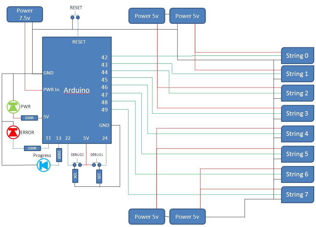
This project develops a Christmas lights controller for GE Color Effects lights, enabling programmed control of up to eight sets of lights. It includes a function-specific language for programming light patterns and an emulation environment for testing programs before...
In the production of LCD projectors, the primary factor threatening the lifespan of the LCD screen is the temperature generated by halogen lamps. The multi-function controller designed by this circuit is highly effective for protecting liquid crystal projectors. The...
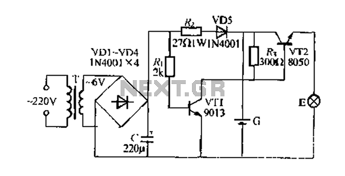
Figure 282 illustrates a simple emergency lamp circuit designed to activate during a power outage. The circuit utilizes a transformer (T) for voltage stepping, diodes (VD1 to VD4) for rectification, and a capacitor (C) for smoothing the output. During...
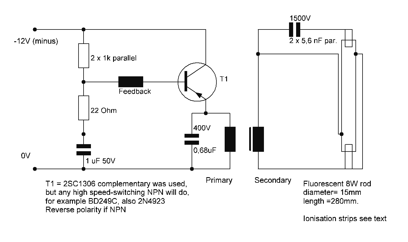
Starting a fluorescent lamp on an inverter can be challenging due to the trade-offs involved in achieving optimal operating efficiency with 12V drivers. Fluorescent lamps require a specific starting voltage to ionize the gas within the tube and initiate the...
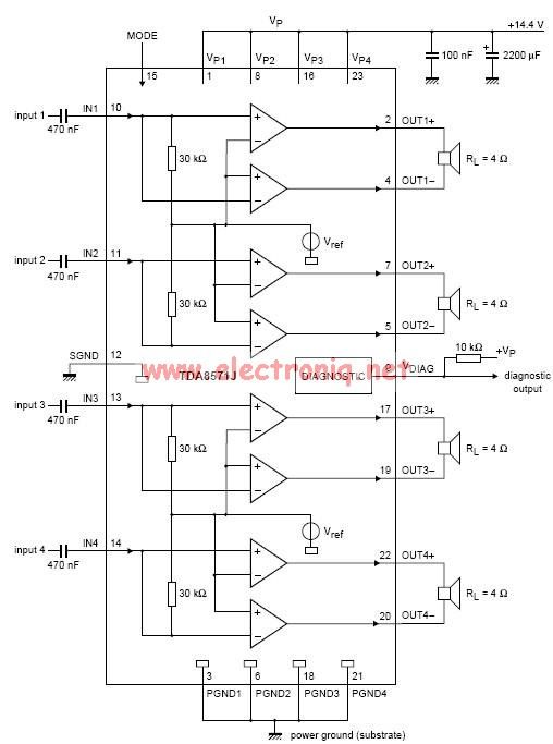
This electronic circuit diagram represents an audio power amplifier utilizing the TDA8571J integrated circuit. It is a class-B output amplifier configured in a BTL (Bridge-Tied Load) arrangement, featuring four amplifiers, each with a gain of 34 dB. The main...