
Voltage-mode control and compensation: Intricacies for buck regulators

Voltage mode control is a widely used method in switching power supplies, particularly in buck converters. This technique regulates the output voltage by comparing it to a reference voltage and adjusting the duty cycle of the switching element accordingly. The control loop's stability and transient response are critical parameters that must be optimized to ensure reliable operation across varying load conditions.
Compensation in voltage mode control is necessary to achieve stable operation. It involves the design of a compensation network that shapes the frequency response of the control loop. Common compensation techniques include Type I, Type II, and Type III compensators, each offering different trade-offs in terms of phase margin, bandwidth, and transient response. The selection of the appropriate compensation scheme depends on the specific application requirements, load characteristics, and desired performance metrics.
When designing a buck converter, it is important to consider the following elements: input and output capacitors, inductor selection, diode characteristics, and PCB layout. Input capacitors must be chosen to handle the input voltage ripple, while output capacitors affect the output voltage ripple and transient response. Inductor selection impacts the efficiency and current ripple, and the diode must be rated for the expected current and voltage conditions.
Additionally, PCB layout plays a significant role in the performance of the buck converter. Proper grounding, trace widths, and component placement are crucial to minimize parasitic inductance and resistance, which can adversely affect the regulator's performance.
In summary, a comprehensive understanding of voltage mode control and compensation is vital for the effective design of buck regulator circuits. Proper selection of components and careful attention to layout will enhance the performance and reliability of the power supply design.Before designing with one of today`s powerful buck regulator ICs, you`ll want a thorough understanding of voltage mode control and compensation. .. 🔗 External reference
Related Circuits
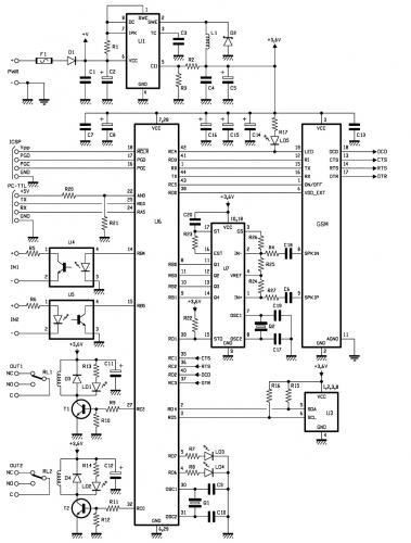
.jpg)
This is a general-purpose remote control project utilizing programmable PIC microcontrollers (PIC16F628, PIC16F630, PIC16F684). Schematics are provided for using infrared (IR) or radio frequency (RF) media. For those unfamiliar with microcontroller programming, fixed encoder and decoder integrated circuits can...
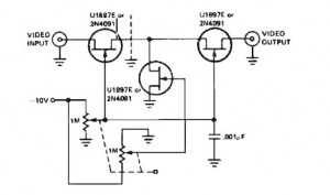
A variable gain amplifier controlled by voltage, functioning as a video amplifier. It utilizes three Field Effect Transistors (FETs) of type U1897E, which can be substituted with 2N4091. The described variable gain amplifier is designed to adjust its gain based...
This article explains the principle of the Audison LR604XR amplifier. The principle is straightforward; it is recommended to combine the text with a careful reading of the complete schematic. To fully understand this principle, it is advisable to review...
This is a small circuit that provides extra security for radio controlled models. When the signal from the transmitter fails, grab the circuit and set the servo connected to a preset position. The circuit is built around a CMOS...
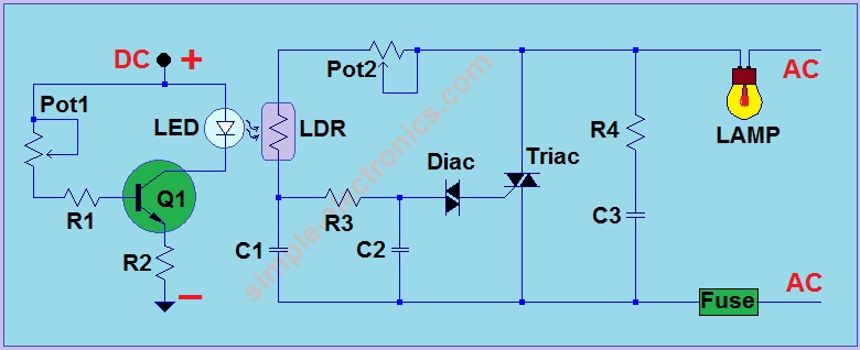
This is another AC light dimmer, with the primary distinction being that its control circuit is isolated from the AC line, making it much safer to use. The circuit can operate on both 120V and 220V AC lines. Note:...
Introduction In this post, the latest application developed from the modular remote control project initiated in the April issue is presented. The modular remote control system is designed to enhance user interaction with various electronic devices through a flexible and...