Extra security for radio controlled alarms
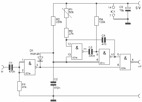
This is a small circuit that provides extra security for radio controlled models. When the signal from the transmitter fails, grab the circuit and set the servo connected to a preset position. The circuit is built around a CMOS IC, the 4093 with 4 Schmitt trigger NAND gates. IC1b and IC1c together a astable multivibrator, which generates pulses for the servo. When a transmitter signal does not and this is the input signal is available at the output. More: With the servo position P1 can be set upon failure. The circuit is also used as a servo tester by the entrance not to join. R1 = 47 kOhm R2 = 220 kOhm R3 = 27 kOhm R4 = 120 kOhm P1 = 50 kOhm C1, C2 = 470 nF C3 = 220 nF C4 = 47 nF C5 = 10 uF D1 = 1N4148 IC1 = CMOS IC 4093
The described circuit serves as a fail-safe mechanism for radio-controlled models, ensuring that in the event of a signal loss from the transmitter, the servo is positioned to a predetermined location. The core of the circuit is the CMOS IC 4093, which contains four Schmitt trigger NAND gates. Specifically, gates IC1b and IC1c are configured as an astable multivibrator, generating a continuous pulse train that drives the servo motor.
The operation of the circuit begins with the transmitter sending a signal to the receiver. Under normal conditions, this signal is processed, allowing the servo to operate as intended. However, if the signal is interrupted, the circuit activates the astable multivibrator, which produces pulses that control the servo's position. The timing and frequency of these pulses can be adjusted based on the values of the resistors and capacitors used in the circuit.
The resistor values are as follows: R1 is 47 kΩ, R2 is 220 kΩ, R3 is 27 kΩ, and R4 is 120 kΩ. The potentiometer P1, with a value of 50 kΩ, allows for fine-tuning of the servo position in case of a signal failure. Capacitors C1 and C2 are both 470 nF, C3 is 220 nF, C4 is 47 nF, and C5 is 10 µF. The diode D1, a 1N4148, is included to protect the circuit from reverse polarity or voltage spikes.
Additionally, the circuit can function as a servo tester when the transmitter is not connected. This feature allows for testing the servo's operation independently, ensuring that the servo is functioning correctly before deployment in a model. Overall, this circuit design enhances the reliability of radio-controlled systems by providing a safeguard against signal loss, making it an essential component for hobbyists and professionals alike.This is a small circuit that provides extra security for radio controlled models. When the signal from the transmitter fails, grab the circuit and set the servo connected to a preset position. The circuit is built around a CMOS IC, the 4093 with 4 Schmitt trigger NAND gates. IC1b and IC1c together a astabiele multivibrator, which generates pulses for the servo. When a transmitter signal does not and this is the input signal is available at the output. With the servo position P1 can be set upon failure. The circuit is also used as a servo tester by the entrance not to join. R1 = 47 kOhm R2 = 220 kOhm R3 = 27 kOhm R4 = 120 kOhm P1 = 50 kOhm C1, C2 = 470 nF C3 = 220 nF C4 = 47 nF C5 = 10 uF D1 = 1N4148 IC1 = CMOS IC 4093 🔗 External reference
