
Voltage-to-current converters

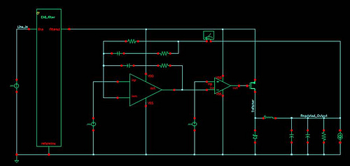
The voltage-to-current converter circuit operates by converting an input voltage signal into a proportional output current. The fundamental relationship governing the output current (I_out) is defined by the equation I_out = V_in / R, where V_in is the input voltage and R is the resistance connected in the feedback loop.
To achieve negative output currents, a PNP transistor can be utilized. This configuration allows for the inversion of the current flow, making it suitable for applications requiring negative current outputs. For applications demanding higher precision and improved linearity, substituting the single PNP transistor with a Darlington pair is advisable. The Darlington configuration consists of two transistors that provide a high current gain, thereby enhancing the performance of the converter.
The design of the circuit must consider factors such as power supply voltage, load characteristics, and thermal management to ensure reliable operation, especially when controlling currents in the range of several amps. Adequate heat sinking may be required to dissipate excess heat generated by the transistors under load conditions.
Unity gain compensation is a critical aspect of the circuit design, ensuring stability across a wide frequency range. This compensation technique involves adding a capacitor in the feedback loop, which helps to mitigate potential oscillations and ensures that the converter maintains a stable output under varying load conditions.
Overall, this voltage-to-current converter design offers versatility and precision for various applications, including signal conditioning, actuator control, and driving loads that require specific current levels.A simple voltage-to-current converter is shown in the figure. The current out is 0t or Vjn/R. For negative currents, a pnp can be used and, for better accuracy, a Darlington pah-can be substituted for the transistor. With careful design, this circuit can be used to control currents of many amps. Unity gain compensation is necessary.
Related Circuits
This circuit is designed to produce square waves by converting a sine wave obtained from an existing generator. A key feature is that it requires no external power source, allowing for simple connection between a sine wave generator and...
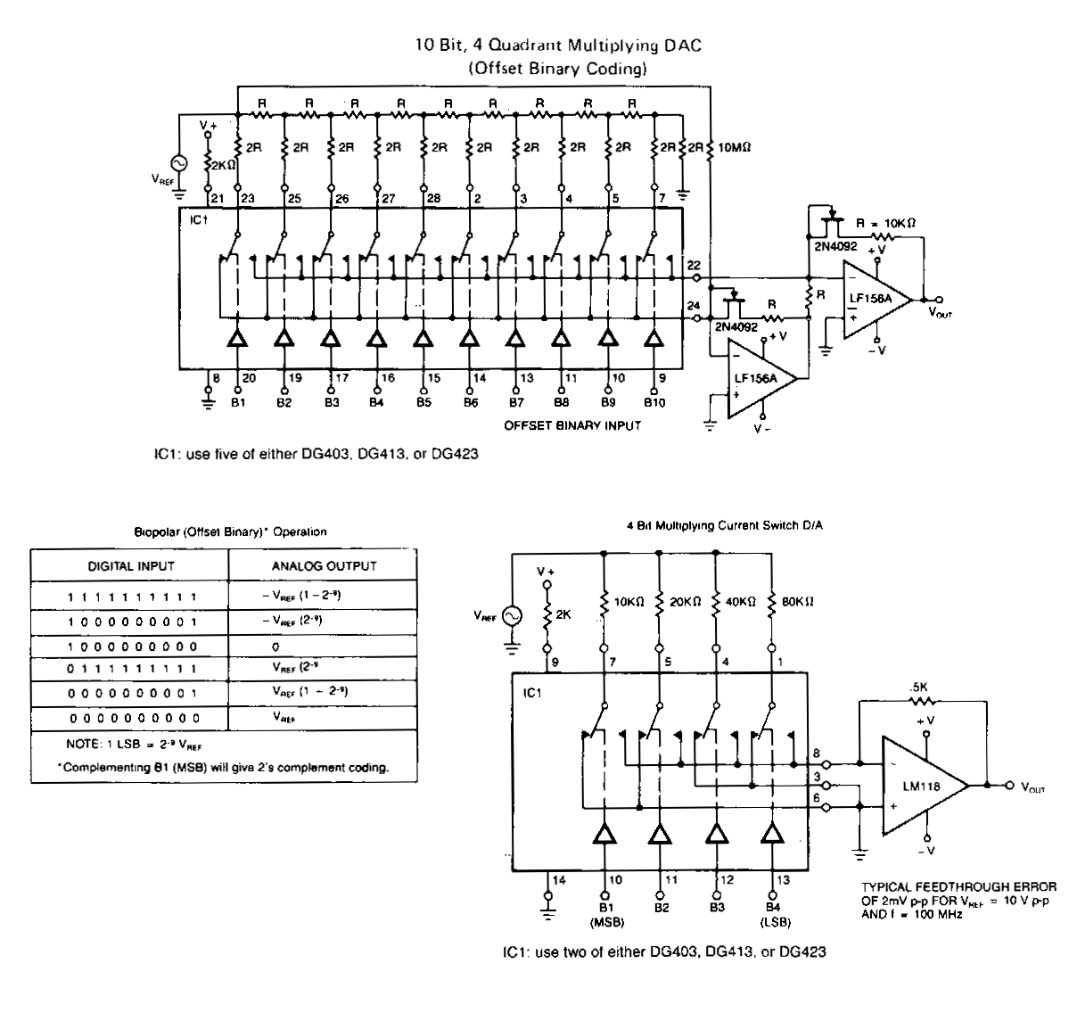
The following application circuits are designed to demonstrate several key concepts: A 2 kΩ resistor should be placed in series with the voltage source to limit supply current and mitigate negative ringing on the bit inputs. Temperature compensation for...
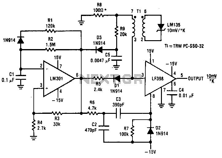
Both converters utilize CMOS inverters. Figure 105-1A illustrates a free-running circuit where both pulse duration and pulse pause are influenced by the temperature of diode D8. This configuration is suitable for applications where synchronization between the converter and other...
Connect with Cadence technologists and peers in the Cadence Community. Stay informed about technology trends, news, and opinions through blogs, forums, and social networking. The Cadence Community serves as a collaborative platform for professionals in the electronics design automation (EDA)...
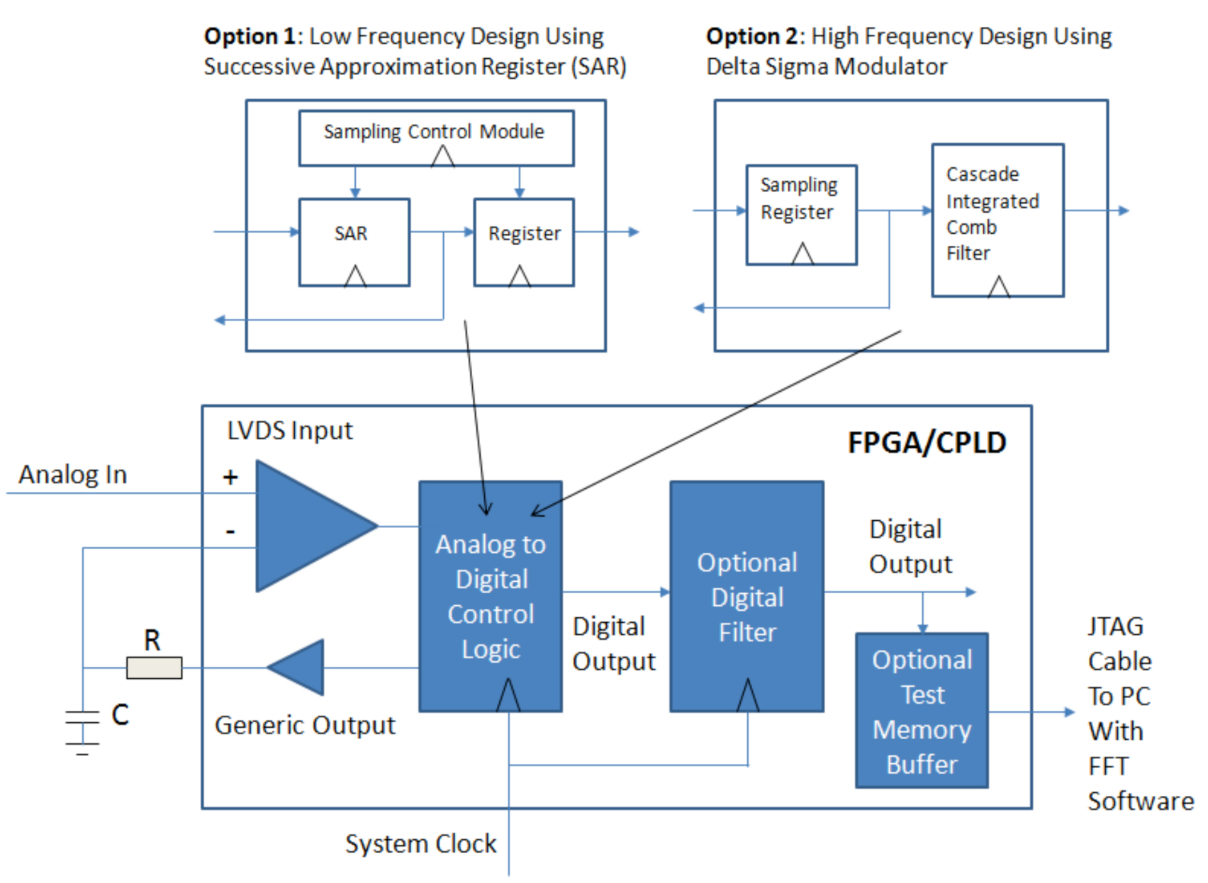
Designers of digital systems are familiar with implementing the remnants of their digital design by using FPGAs and CPLDs to connect various processors, memories, and standard function components on their printed circuit board. In addition to these digital functions,...
This document outlines the layout considerations for switch-mode DC-DC converter printed circuit boards (PCBs) aimed at minimizing switching noise and electromagnetic interference (EMI). The layout of switch-mode DC-DC converter PCBs is critical in ensuring efficient operation and compliance with electromagnetic...