
Voltage-to-pulse duration converter

This circuit utilizes an operational amplifier to amplify input voltage levels, which are then processed by a timer IC to generate corresponding pulse durations. The op amp serves as a voltage comparator, where it compares the input voltage against a reference voltage. When the input exceeds the reference level, the op amp output switches states, creating a pulse.
The timer IC, such as the 555 timer, can be configured in monostable mode to produce a single output pulse of a specified duration when triggered by the op amp's output. This duration can be adjusted by varying the resistor and capacitor values connected to the timer, allowing for precise control over the pulse width in relation to the input voltage.
The design ensures that the output frequency remains constant, irrespective of variations in the input voltage, which is crucial for applications requiring stable signal processing. The overall accuracy of the system, exceeding 1%, is achieved through careful selection of components and calibration of the circuit to minimize errors from drift and noise.
This circuit can be employed in various applications, including analog-to-digital conversion, signal conditioning, and timing applications, where accurate pulse generation is essential. The combination of the op amp and timer IC provides a versatile solution for converting voltage levels into precise pulse durations while maintaining signal integrity. Accuracies to better than 1% can be obtained with this circuit (a), and the output signals (b) still retain the original frequency, independent of the input voltage. Voltage levels can be converted to pulse durations by combining an op amp and a timer IC.
Related Circuits
Optimize the layout of the MAX16974/MAX16975/MAX16976 high-performance DC-DC converters, which are standard buck controllers designed for automotive applications. The MAX16974, MAX16975, and MAX16976 are advanced DC-DC buck converters specifically tailored for automotive environments. These devices are engineered to deliver high...
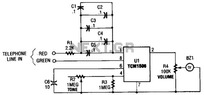
The circuit utilizes the TCM1506 ring detector/driver integrated circuit, which is a monolithic IC designed to replace mechanical bells in telephones. It is powered and activated by the telephone line's ringing signal, which ranges from 40 to 150 V...
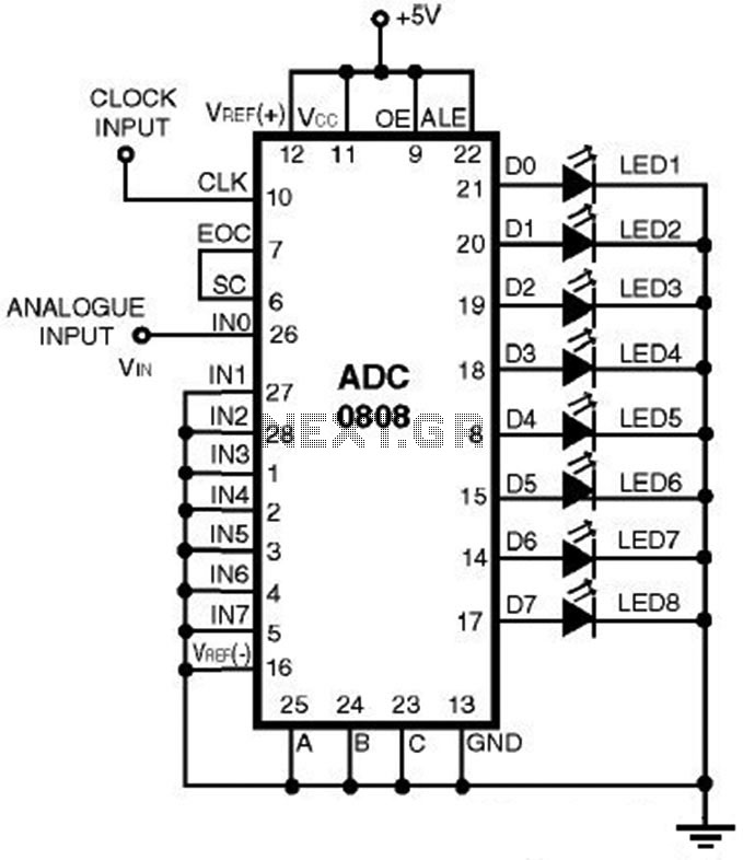
This is a straightforward analog-to-digital converter circuit utilizing an 8-bit analog-to-digital converter (ADC0808). Typically, an analog-to-digital converter (A/D Converter / ADC) necessitates interfacing with a microprocessor to convert analog signals. The ADC0808 is a widely used 8-bit A/D converter that...
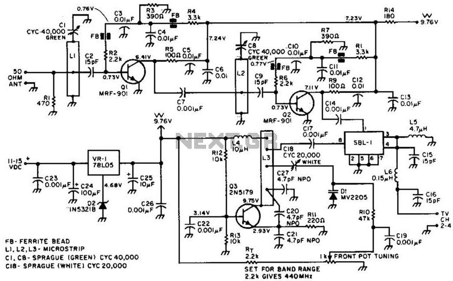
Most ATV (Amateur Television) transmitters operate using a Double Sideband (DSB) signal, while commercial television stations utilize a Vestigial Sideband (VSB) signal. This distinction is leveraged in this converter to utilize the lower sideband, thereby reducing interference from repeaters...
This is a 35.3 to 10.7 MHz converter circuit. It converts the 35.3 MHz signal coming from a VHF/UHF tuner down to an FM tuner to decode the TV audio in FM. The 35.3 to 10.7 MHz converter circuit is...
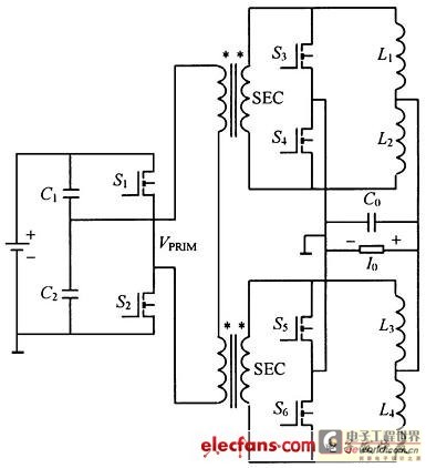
This structure significantly reduces electric current ripple on the filtering capacitance, thereby minimizing the inductive magnitude and overall size of the DC-DC converter. The converter operates at a switching frequency of 100 kHz with an input voltage of 48V....