
ADC0808 - Simple Analoque to Digital Converter

The ADC0808 is a widely used 8-bit A/D converter that can convert analog signals into digital data. It features a parallel output, which allows for direct interfacing with microprocessors and microcontrollers. The conversion process involves sampling an analog voltage and converting it into a corresponding 8-bit binary number, where the output can represent values from 0 to 255.
The circuit typically consists of the ADC0808 connected to an analog input source, such as a sensor, and a microprocessor that reads the digital output. The ADC0808 requires a reference voltage, which determines the range of analog input values that can be converted. This reference voltage is often set to a standard value, such as 5V, allowing for an input range of 0 to 5V.
To initiate the conversion process, the microprocessor sends a start signal to the ADC0808. The ADC then samples the input voltage, and after a short delay, the digital output becomes available. The microprocessor can then read the 8-bit data from the ADC's output pins, which correspond to the sampled analog voltage.
In addition to the ADC0808, the circuit may include additional components such as operational amplifiers for signal conditioning, resistors for biasing, and capacitors for noise filtering. Proper layout and grounding techniques are essential to minimize noise and ensure accurate conversions.
Overall, the ADC0808 circuit is a fundamental building block in many electronic systems where analog signals need to be processed or monitored digitally. Its simplicity and effectiveness make it suitable for various applications, including data acquisition, instrumentation, and control systems.This is a very simple analoque to digital converter circuit based on 8-bit analog-to-digital converter ADC0808. Typically analogue-to-digital converter (A/D Converter / ADC) requires interfacing through a microprocessor to convert analogue..
🔗 External reference
Related Circuits
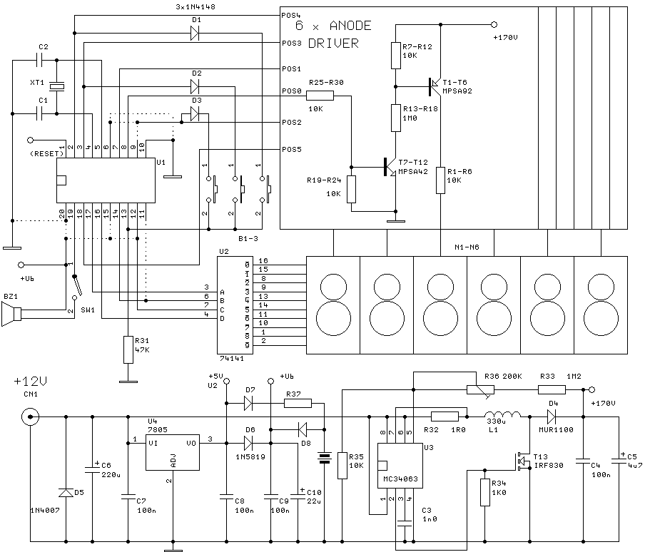
The clock will have 6 digits and time setting will be done by means of a few buttons. I will try to use the most common types from widely used microcontroller families of miscellaneous producers. I will write the...
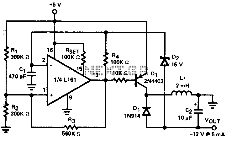
A low power DC to DC converter is created by integrating a flyback circuit with a square wave oscillator. The operating frequency is set at 20 kHz to reduce the size of the inductor (L1) and capacitor (C2). Regulation...
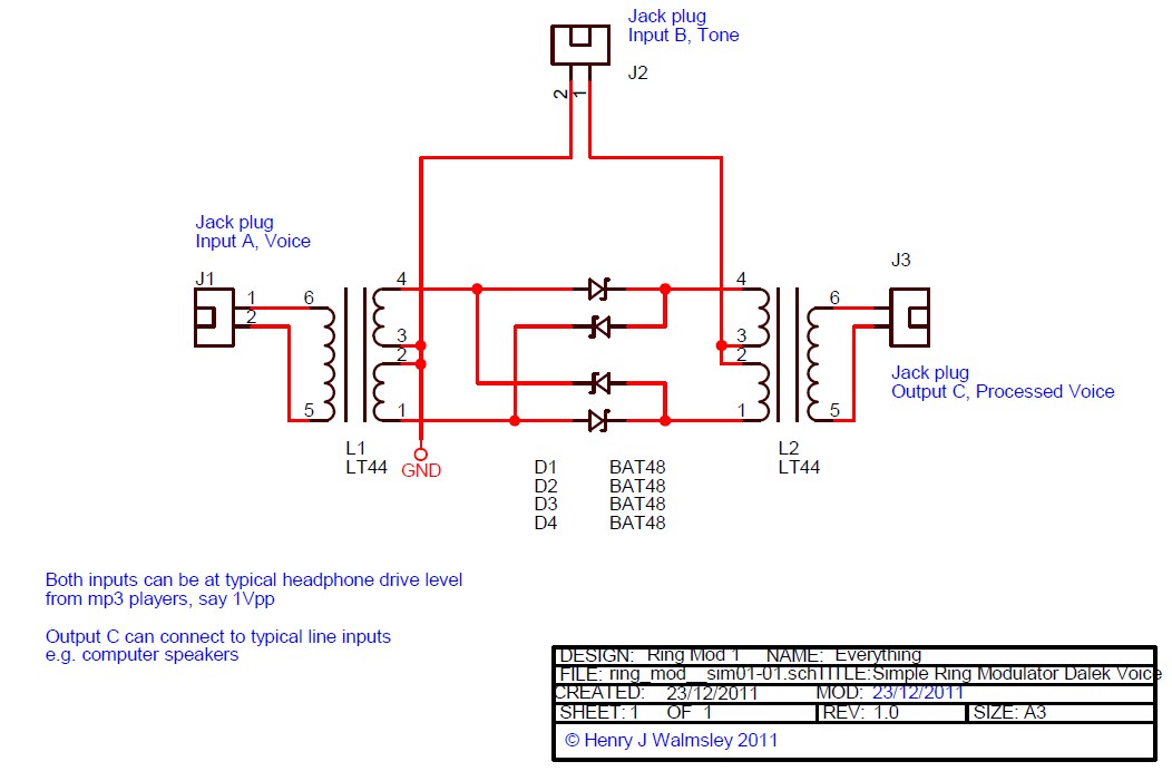
This is a simple ring modulator circuit designed to create interesting analog sound effects using two audio sources and an amplifier or recording device. With the widespread availability of MP3 players and powered computer speakers, building this circuit is...
The 555 IC is configured in an astable mode, producing a frequency that remains constant and is independent of the duty cycle. The total resistance (Rcharge + Rdischarge, considering the diode) is fixed at 22 kΩ, yielding a frequency...
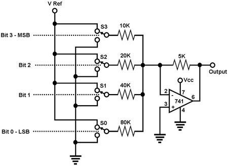
The circuit depicted in Figure 1 is a straightforward 4-bit digital-to-analog converter (DAC). It functions as a simple operational amplifier (op-amp) summer circuit, configured to produce an output voltage that is proportional to the sum of the input voltages....
This chapter shows how to connect an analogue signal to a PIC. An analogue signal is similar to a sine wave and is generally less than 5v (5,000mV) in amplitude. Low-level signals are generally expressed in mV, to make...