
vu meter circuit

The NL3ASD schematic pages feature a comprehensive design for a LED VU meter that employs the UAA180 IC, known for its audio signal processing capabilities. The UAA180 is specifically designed to drive LED indicators based on the amplitude of audio signals, making it suitable for visualizing audio levels in various applications.
The schematic typically includes a power supply section, which may consist of a voltage regulator to ensure stable operation of the UAA180. The input section connects to an audio source, where the audio signal is fed into the UAA180 for processing. The IC's internal circuitry analyzes the incoming audio signal and generates control signals for the LED drivers.
The output section of the circuit is designed to drive multiple LEDs arranged in a bar graph format or a single LED that varies in brightness according to the audio level. The schematic may also incorporate resistors to limit current to the LEDs, ensuring they operate within safe parameters. Capacitors may be included for filtering to smooth out any noise in the power supply or audio signal.
Overall, the design emphasizes clarity and functionality, allowing for easy interpretation and implementation in various audio applications, such as mixers, amplifiers, or standalone audio level indicators. The schematic serves as a valuable resource for engineers and hobbyists interested in constructing their own LED VU meters.The NL3ASD Schematic Pages - Here Can You Find The Schematics Of A Schematic Of A LED VU Meter With The UAA180.. 🔗 External reference
Related Circuits

This circuit includes an amplifier designed to deliver +10 dBm to an SBL series (Mini-Circuits) or a similar type of doubly-balanced mixer assembly. The circuit parameters are specified for 80 to 90 MHz crystals, although the values of the...
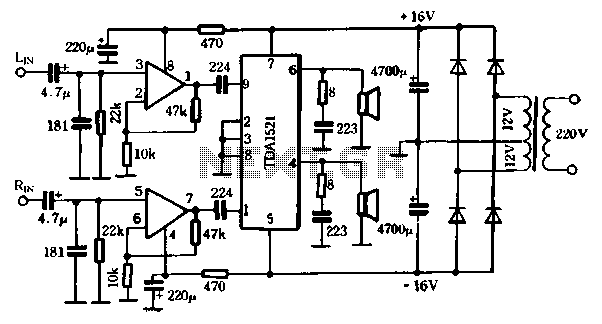
The first power amplifier circuit illustrated in Figure 5-88 utilizes the NE5532 operational amplifier, configured as a line amplifier, and features the TDA1521 power amplifier. This circuit operates with a dual power supply and eliminates the need for coupling...
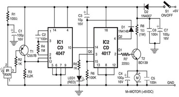
The following circuit illustrates an Infrared Toy Car Motor Controller Circuit Diagram. This circuit is based on the 4017 IC. Features: operating at .. The Infrared Toy Car Motor Controller Circuit utilizes a 4017 Decade Counter IC, which is integral...
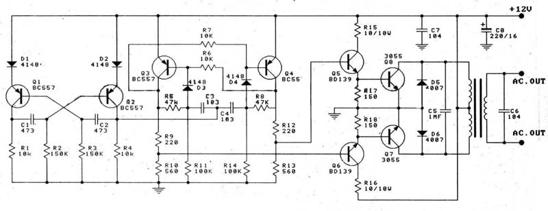
A 12V car battery is recommended as the input for this circuit, utilizing the 2N3055 transistor as the amplifier. This configuration can deliver a power output of up to 100W, making it suitable for use in battery chargers, emergency...
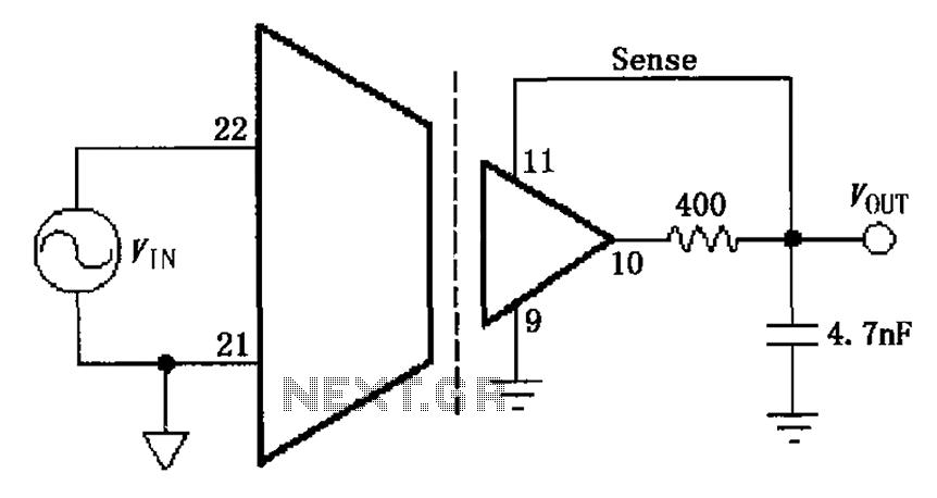
The ISO103 ripple reduction circuit features an output circuit combined with an RC high-pass filter designed to filter out output ripple without impacting the direct current (DC) characteristics. Under specific conditions, the circuit is capable of reducing an 800...
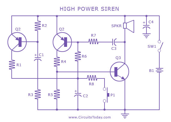
A siren circuit diagram that generates a strong, high-power siren or alarm sound using complementary transistor pairs BC 557 and BC 337, arranged as an oscillator. The described siren circuit employs a pair of complementary transistors, BC 557 (a PNP...