
VU Meter Circuit with 10 LED

The VU meter circuit utilizes a series of 10 light-emitting diodes (LEDs) to visually represent audio signal levels. The fundamental operation of the circuit is based on converting an audio signal into a varying voltage, which is then used to drive the LEDs. Typically, the circuit includes an operational amplifier (op-amp) configured as a rectifier to convert the AC audio signal into a DC voltage. This DC voltage is proportional to the amplitude of the audio signal.
The LEDs are arranged in a linear fashion, with each LED representing a specific range of audio levels. A resistor network may be used to limit the current through each LED, ensuring they illuminate at appropriate brightness levels without exceeding their maximum ratings. Additionally, a smoothing capacitor can be included to provide a more stable voltage to the LEDs, reducing flicker and providing a more consistent visual indication of the audio level.
Power for the circuit can be supplied from a low-voltage DC source, such as a battery or a regulated power supply, making it suitable for portable applications. The simplicity of the design allows for easy integration into various audio equipment, providing a clear and immediate visual representation of sound levels, which can be particularly useful in live sound environments or audio mixing situations. Overall, this LED VU meter circuit is an effective tool for monitoring audio signals with minimal complexity.Here is VU meter 10 LED circuit, This simple LED VU meter has only a few parts but it is useful as an indicator for the sound. The circuit is built around an. 🔗 External reference
Related Circuits
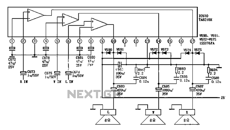
The audio circuit depicted in the figure is commonly utilized in color television systems. The pin functions and reference voltages for the TA8218AH are as follows: Pin 1: 1.9V - inverting input; Pin 2: 2.1V - R-channel audio signal...
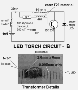
This circuit illustrates a 1.5V LED power supply circuit diagram. Features include the requirement of a step-up transformer (40:60) for easy provision. Components include an integrated circuit (IC). The described circuit functions as a power supply specifically designed for driving...
An inductance meter can be a valuable test instrument for hobbyists. However, few people own them due to their high price. The Inductance Meter Adapter described in this article is a circuit that, when connected to a digital multimeter...
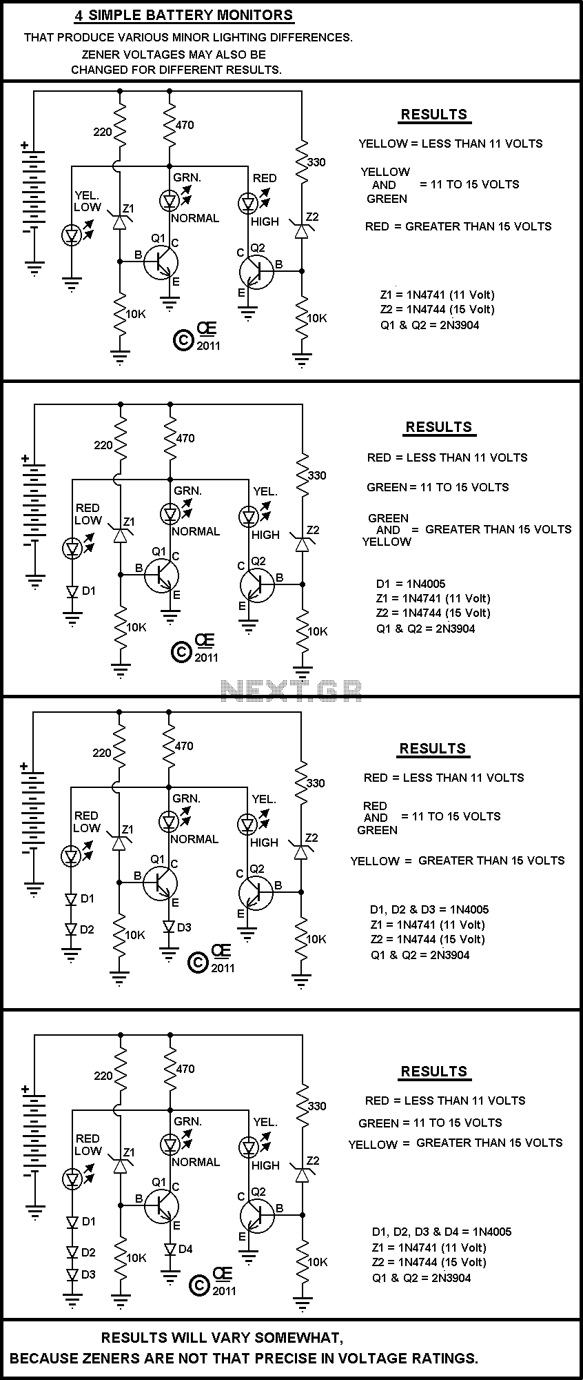
A Very Simple circuit and some Variations. Play with it. All parts are cheap and should be easily obtained. None are very critical. The circuit in question is a basic electronic assembly designed for educational purposes and experimentation. It typically consists...
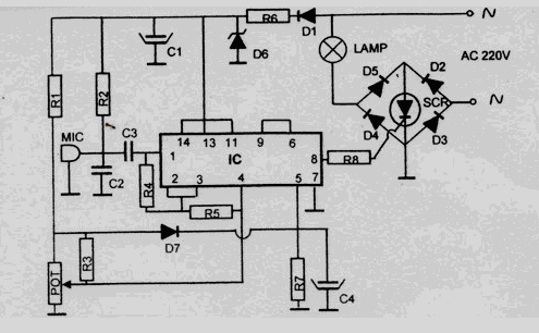
This disco lamp circuit is not a voice-operated switch (VOX) because it cannot differentiate between musical sounds and human voices. Instead, it is sound-activated. An interesting application of this circuit is to control disco lighting automatically using the musical...
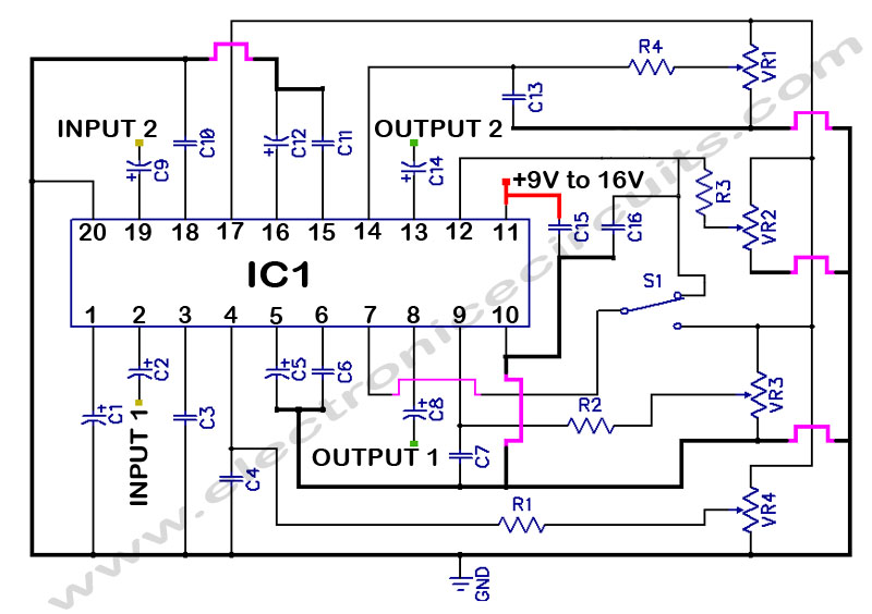
LM1036 Stereo Tone (Bass, Treble, Volume, Loudness, Balance) Controller Circuit. The LM1036 is a DC controlled tone (bass/treble), volume, and loudness controller designed for audio applications. The LM1036 circuit serves as an integrated solution for controlling various aspects of audio...