
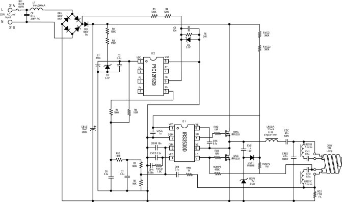
15V LED Power Supply

The described circuit functions as a power supply specifically designed for driving LEDs at a voltage of 1.5V. The step-up transformer plays a crucial role in this configuration, as it converts a lower input voltage into a higher output voltage suitable for LED operation. The specified transformer ratio of 40:60 indicates the turns ratio, meaning that for every 40 turns on the primary side, there are 60 turns on the secondary side, resulting in a voltage increase.
The circuit typically comprises several key components: a step-up transformer, an integrated circuit (IC) that regulates the output voltage and current, and additional passive components such as resistors and capacitors that stabilize the circuit's performance. The IC may also include features for thermal protection and overcurrent protection to ensure the reliability and longevity of the LED.
In operation, the circuit takes a lower input voltage, which is then stepped up by the transformer. The output from the transformer is rectified and filtered to provide a stable DC voltage suitable for powering the LED. The design must consider the forward voltage and current requirements of the LED to ensure optimal performance and prevent damage.
Overall, this circuit is an efficient solution for powering LEDs from a low voltage source, making it suitable for various applications, including battery-operated devices and low-power lighting systems.This circuit shows about 1,5V LED Power Supply Circuit Diagram. Features: needed a step up transformer (40:60)easily provide. Component: IC, .. 🔗 External reference
Related Circuits
Electronic ballasts for dimming fluorescent lamps require a control interface for the user to set the desired lamp brightness level. Existing interface circuits include a 1-to-10 Vdc interface, a digitally-addressable lighting interface (DALI), triac-based wall dimmers, three-way lamp sockets,...
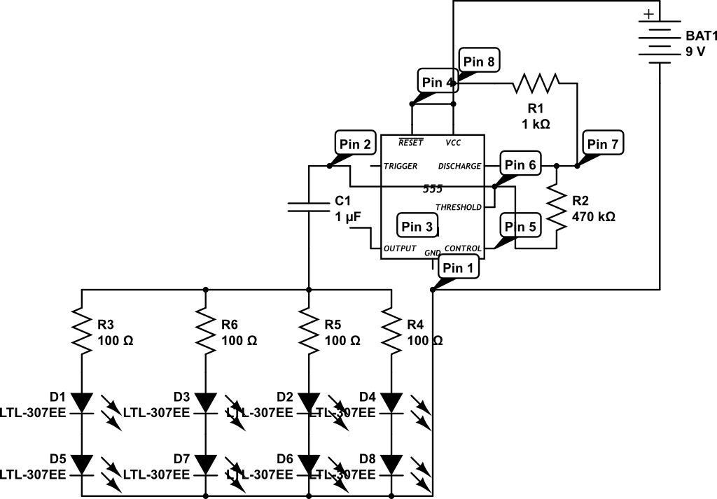
LEDs are rated for a continuous current of only 30 mA, while this circuit operates them at approximately 50 mA. Although this is acceptable for low duty cycles with short pulses, the intended design has a high duty cycle....
Switching to alternative power sources can lead to savings on electricity bills. The photovoltaic module or solar panel discussed here has a power output of 5 watts. Under full sunlight conditions, the solar panel generates 16.5V and can provide...
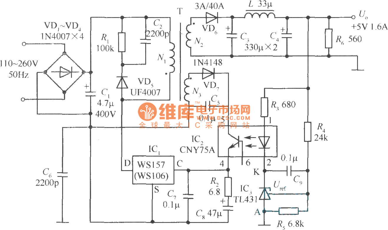
The +5V, 1.6A precision switching power supply circuit is depicted in the figure. This circuit utilizes a photoelectric coupler (CNY75A) and an adjustable precision parallel regulator (TIA31). R3 serves as the current limiting resistor, while R4 and R5 function...
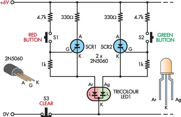
This is a modern twist on the classic game of noughts and crosses, utilizing nine 10mm tri-color LEDs arranged in a 3 x 3 grid. One player has nine red buttons while the other player has nine green buttons,...
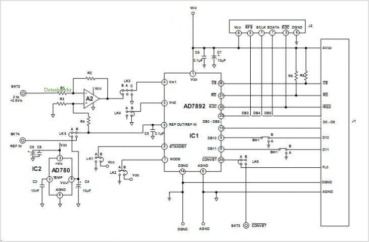
This data sheet describes the evaluation board for the AD9834 direct digital synthesizer (DDS). The AD9834 is a numerically controlled oscillator that utilizes a phase accumulator, a sine look-up table, and a 10-bit DAC. The AD9834 can operate with...