
W7800 by the application circuit composed of power supply tracking
The W7800 voltage regulator is designed to provide a stable output voltage, making it suitable for various applications where a consistent power supply is critical. Its integration allows for reduced component count and improved reliability in electronic circuits. The F007 operational amplifier complements the W7800 by enabling precise tracking of the output voltage, which is particularly important in systems where the positive and negative supplies must remain in sync.
The operational amplifier in the F007 configuration is connected in a feedback loop that monitors the output voltage of the W7800. By utilizing high-precision resistors, the circuit achieves accurate control over the output, ensuring that any variations in the positive supply are mirrored by the negative supply. This tracking mechanism is essential in applications such as dual-supply op-amp circuits, where maintaining a balanced supply voltage is crucial for optimal performance.
In summary, the combination of the W7800 and F007 creates a robust solution for power supply regulation, where both positive and negative voltages are managed efficiently. The design emphasizes precision and stability, making it an ideal choice for sensitive electronic systems that require reliable power management. As shown in FIG W7800 is positive Integrated voltage regulator and F007 consisting of an operational amplifier power supply tracking application circuit. Some use positive and negative of the power supply, a negative supply required to track changes in the positive supply. Figure W7800 do with the positive supply, operational amplifiers and power tubes can be traced negative supply. Shown by two identical (higher precision) of 4.7 k resistor, the potential of the F007s control inputs at zero level, and the output of the F007 with the power to control the negative loop regulator to maintain the output of the negative positive output tracking.
F007 op amp power supply with positive and negative input voltage source.
Related Circuits

The digital circuit that is particularly useful is the One-Shot circuit, also known as a monostable multivibrator circuit. This circuit exhibits a specific behavior where it generates a single output pulse in response to an input trigger. The One-Shot circuit,...
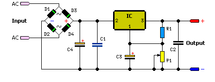
The simple method to power your projects is illustrated in the circuit diagram of a regulated power supply. This compact power supply delivers a stable voltage. This regulated power supply circuit is designed to convert an unregulated input voltage into...
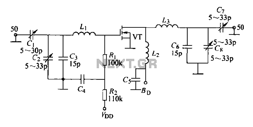
A 175 MHz high-frequency amplifier circuit utilizing a field-effect transistor (FET) is presented. The field-effect transistor used is the 3D04H, along with its associated components and parameters. The 175 MHz high-frequency amplifier circuit is designed to amplify signals in the...
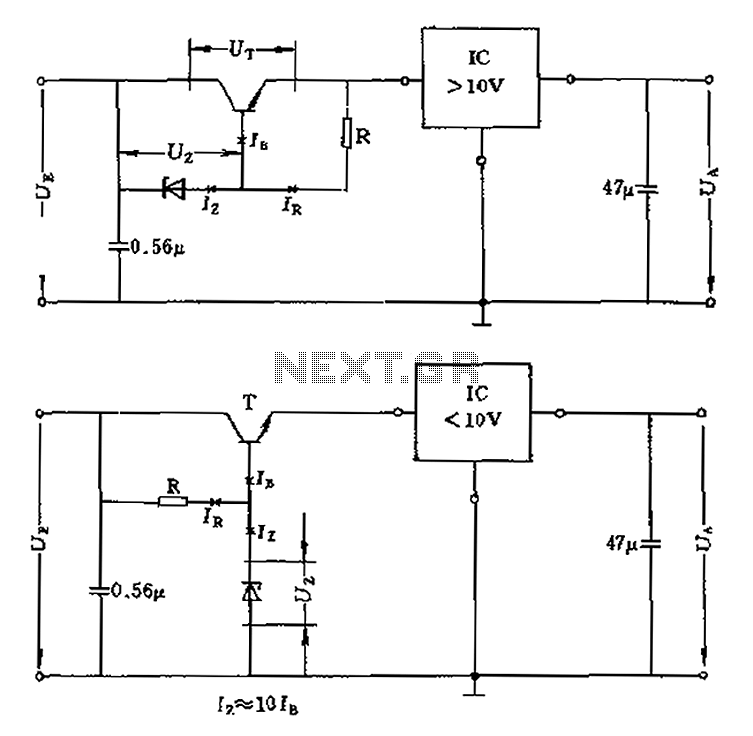
The voltage equation Ue = Ut + Ur + Ua indicates that the transistor voltage Ut will determine the maximum output voltage Ua. Additionally, Ur must be 2V. The voltage regulator's voltage value depends on the selection of Uz....
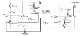
The circuit diagram illustrates the original Kodak MAX Flash Unit, including the semiconductors that comprise the circuit. This diagram represents the unmodified version intended for the standard Kodak model, which should closely resemble the Kodak MAX model, if not...
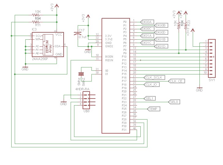
After constructing numerous Nixie Tube Clocks based on online designs, a personal design was developed. This clock utilizes IN-12 Nixie Tubes and an 8-core Propeller Microcontroller. Although the Propeller may be more powerful than necessary for this task, it...