
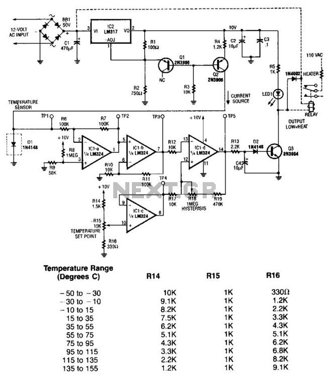
Water alarm circuit

The described circuit features a temperature sensing mechanism that activates when water reaches its boiling point. This mechanism serves a dual purpose: it not only signals an alert (referred to as "the police") but also disconnects the heater's power supply to prevent overheating or potential hazards associated with boiling water.
The core of the system is the temperature sensing element, which is designed to detect temperature changes accurately. When the water temperature exceeds a predefined threshold, the sensor activates a relay or a switch that interrupts the power to the heater, effectively shutting it down. This action is critical for safety, ensuring that the heater does not continue to operate when the water has boiled away, which could lead to equipment damage or fire hazards.
Additionally, the integration of a fluorescent neon light bulb within the starter circuit serves as a visual indicator. This bulb illuminates when the water reaches boiling point, providing a clear and immediate visual cue to the user. The restructuring of the light bulb within the starter enhances the overall functionality of the circuit by combining temperature sensing with visual signaling.
Overall, this circuit design emphasizes safety and user awareness in heating applications, leveraging both automatic power cut-off and visual alerts to manage the risks associated with boiling water.When the water boils, it is not only the police, but also cut off the heater power. Temperature sensing element with a fluorescent neon light bulb restructuring within the starter.
Related Circuits
The LM35 temperature sensor outputs 10 mV/C for each degree Celsius above 0°C. At 20°C, the output voltage is calculated as 20 × 10 = 200 mV. The circuit consumes minimal power. Additionally, the load resistance should not be...

The circuit employs a widely used Sharp IR module (the Vishay module may also be utilized). The pin numbers indicated in the circuit pertain to both the Sharp and Vishay modules. For other modules, it is recommended to consult...
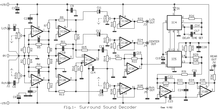
Surround Sound Decoder circuit diagram. The circuit's operation begins when the stereo sound signal carries surround sound information through the master volume section. This drives the Left channel (Lch), which is connected to Model TL072 IC1A and IC1B, with...

Circuit for applying a DC-coupled FM or PPM to a 555 configured as an oscillator. IC-1 is a Motorola MC-1374P, and IC-2 is a National LH0002C. L1 and L2 are Mouser Electronics #421IF200. C1 and C2 are silver mica...

Several integrated circuits (ICs) are currently available that provide a nearly complete FM receiver solution. This project outlines a complete FM receiver circuit that offers excellent receiving and sound qualities. However, from a DIY enthusiast's perspective, the only drawback...

An automatic recording telephone interface circuit is presented, featuring an automatic answering and recording function that requires a reprovisioning or a small solid-state recording chip. The circuit is straightforward, with a quiescent current of less than 20 µA, allowing...