
Water heaters electronic ignition circuit

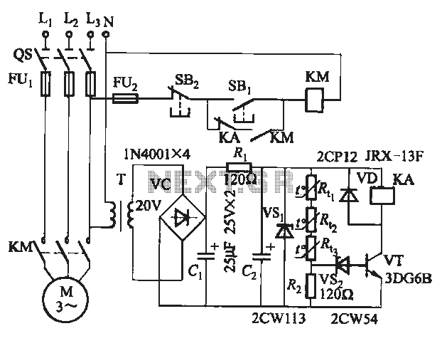
The electronic ignition circuit is designed to initiate the gas supply for a water heater in response to the demand for hot water. The operation begins when the user opens the faucet, which closes switch K, thus connecting the 3V battery to the circuit. This battery provides the necessary power for the entire ignition process.
Initially, capacitor C2 is in a charging state, which prevents transistor VT6 from turning on. This is a crucial step, as it ensures that the circuit does not inadvertently activate while the system is in an idle state. Once C2 has charged sufficiently, it allows the circuit to progress to the next stage.
Simultaneously, capacitor C3 begins to charge. The charging of C3 is vital, as it influences the operation of transistors VT7 and VT8. Once C3 reaches a certain voltage threshold, it enables VT7 and VT8 to conduct. The conduction of these transistors serves as a signal to the gas supply solenoid valve (BK), allowing it to receive power.
As a result, the solenoid valve is energized, which opens the gas valve. This action initiates the flow of gas, preparing the water heater for operation. The design of this circuit ensures that the ignition process is both efficient and safe, as it relies on the controlled charging of capacitors and the sequential activation of transistors to manage the gas supply effectively. Overall, this electronic ignition circuit exemplifies a reliable method for activating a water heater in response to user demand.Electronic ignition circuit for the water heater is shown. When you open the faucet, switch K 3V battery, since the charging C2 need room, so VT6 is off, the power supply while the C3, charging so VT7, VT8 conduction, so that the gas supply (gas) solenoid valve BK start winding is energized, the gas valve open, gas began.
Related Circuits
A project of a 555 tester circuit, the circuit will start blinking LEDs when power is applied, which will indicate that the IC is working correctly. The 555 tester circuit is designed to verify the operational status of the 555...

A field-effect transistor (FET) is utilized in a headphone circuit designed to function as a silencer tube. The circuit integrates L from the digital signal processing unit and R from the audio signal into the headphone jack's mute control...
This schematic diagram illustrates a single-chip Theremin circuit. A Theremin is an electronic musical instrument that detects hand movements to control tones and frequency. The circuit employs two separate Colpitts LC oscillators to generate a beat frequency. The frequencies...
This simple circuit can be utilized to activate various devices, such as microcontrollers, relays, secret alarms, or robot applications. It can also be used to turn on LED1, which remains illuminated as long as the metal plate is touched....
The semiconductor thermistor is an embedded thermal protection element that is sensitive to temperature, with a temperature error of 5 degrees. It offers reliability, a small size (diameter 3.5 mm), and ease of installation, making it suitable for embedding...
When VRI is off, 0 [2 is activated, allowing current to flow through RJ and Ci. When VT1 conducts, charging of C1 begins, causing it to discharge. This results in an inverting charge on C1, making the voltage positive,...