
Water Level Alarm

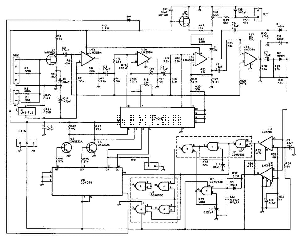
The described circuit functions as a fluid level monitoring system, capable of providing both visual and audible alerts to indicate the fluid level within a designated vessel. The primary components of this circuit typically include a fluid level sensor, an LED indicator, a microcontroller or comparator circuit, and a buzzer for the audible alarm.
The fluid level sensor can be a float switch, capacitive sensor, or ultrasonic sensor, depending on the application requirements. The float switch operates by rising and falling with the fluid level, completing a circuit when the fluid reaches a predetermined height. Capacitive sensors detect changes in capacitance caused by the presence of the fluid, while ultrasonic sensors use sound waves to measure the distance to the fluid surface.
The microcontroller or comparator circuit processes the input from the fluid level sensor. When the fluid level reaches a specified threshold, the microcontroller activates an LED indicator to provide a visual alert. This LED can be configured to illuminate in different colors to indicate various levels (e.g., green for safe levels, yellow for caution, and red for low levels).
In addition to the visual indicator, the circuit incorporates a switchable audible alarm. This alarm is typically a piezoelectric buzzer that emits sound when the fluid level is either too low or too high, depending on the design specifications. The switch mechanism allows users to activate or deactivate the alarm as needed, providing flexibility in monitoring applications.
Power supply considerations for the circuit should include voltage and current ratings that match the components used. A battery or an AC-to-DC power supply can be employed to ensure the circuit operates reliably.
Overall, this fluid level monitoring circuit is suitable for various applications, including domestic settings such as baths and aquariums, as well as industrial contexts like cold storage tanks, ensuring safe and efficient fluid management.A circuit that offers visual indication of fluid level in a vessel, with a switchable audible alarm. Example uses would be to monitor the level of water in a bath or cold storage tank. 🔗 External reference
Related Circuits
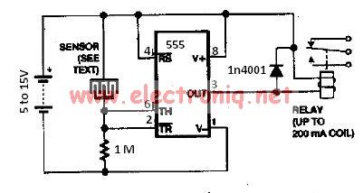
The water sensor circuit utilizes a 555 timer circuit along with common electronic components. It consists of two metal electrodes positioned closely enough that a drop of water can create a conductive bridge between them. If the water is...
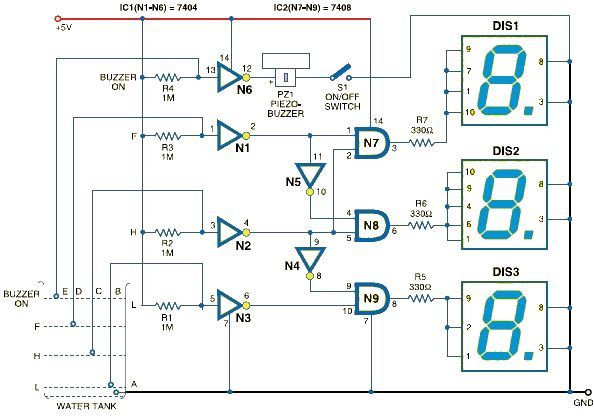
This schematic outlines a simple electronic circuit designed to indicate water levels using a 7-segment display. The circuit shows water levels by displaying 'L', 'H', and 'F' for low, half, and full levels, respectively. It is based on the...
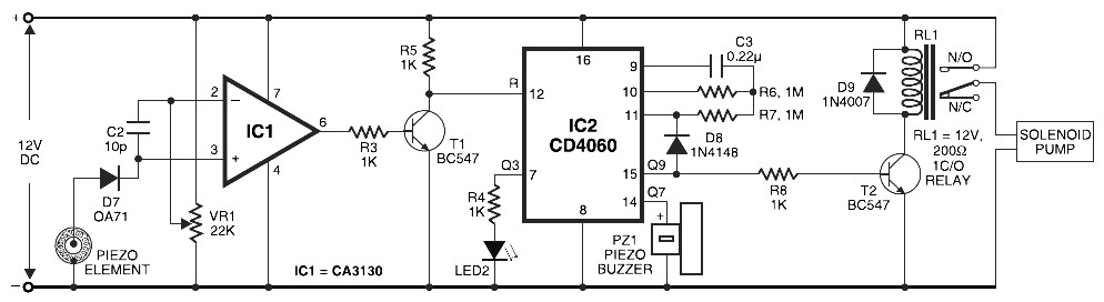
Pyroelectric Fire Alarm System Diagram. The front end of the circuit contains a sensitive signal amplifier constructed close to IC1 (CA3130). It delivers a high output when the temperature near the piezo component raises. IC CA3130 is a CMOS...
The above picture illustrates an audio logic level probe circuit, which consists of a voltage comparator, a multivibrator, and piezoelectric ceramics (HTD). The multivibrator and piezoelectric components together form the audio circuit, which operates at an audio frequency to...
The mine railway connects the national railways and intermediate links of the mining area, serving as an important component of the railway transport network. Statistics indicate that the Chinese mine railway extends over 20,000 kilometers, with numerous road junctions...
This method of automatic level control (ALC) utilizes digitally switched audio attenuators within the signal path. The output level of the system is monitored, compared to a reference level, and audio pads are introduced through analog switches. This technique...