
Water sensor circuit using 555 timer

The water sensor circuit operates on the principle of conductivity detection. The two metal electrodes, when exposed to water, allow current to flow between them, thereby changing the voltage level at the input of the 555 timer. This timer can be configured in either monostable or astable mode, depending on the desired output behavior.
In monostable mode, the circuit will produce a single output pulse when water is detected. The duration of this pulse is determined by the resistor and capacitor values in the circuit. In contrast, when configured in astable mode, the circuit will continuously output a square wave signal, which can be used for applications such as driving an alarm or activating a relay.
The choice of resistor values is crucial for the sensitivity of the sensor. A higher resistor value, such as 2.2 MΩ, increases the circuit's sensitivity to pure water, while a lower value, like 220 kΩ, can help prevent false triggering due to environmental noise or impurities in the water. This adjustability allows for fine-tuning of the sensor's response to different types of liquids.
In addition to the 555 timer and resistors, the circuit may include a capacitor to stabilize the voltage and filter out noise. A diode can also be added to protect the circuit from reverse polarity or voltage spikes. The output from the 555 timer can be connected to various devices, such as LEDs for visual indication or relays for controlling larger loads.
Overall, this water sensor circuit provides a reliable and adjustable solution for detecting the presence of water using basic electronic components, making it suitable for various applications in home automation, leak detection, and irrigation systems.The water sensor circuit is based on a 555 timer circuit and come common electronic components. The water sensor is made by two metal electrodes arranged very close that a drop of water (liquid) will bridge them. If the liquid ( water ) is very pure you may change the resistor value to 2. 2m ohms and if the circuit is give false alarm sensing you may change the value of resistor to 220k. 🔗 External reference
Related Circuits
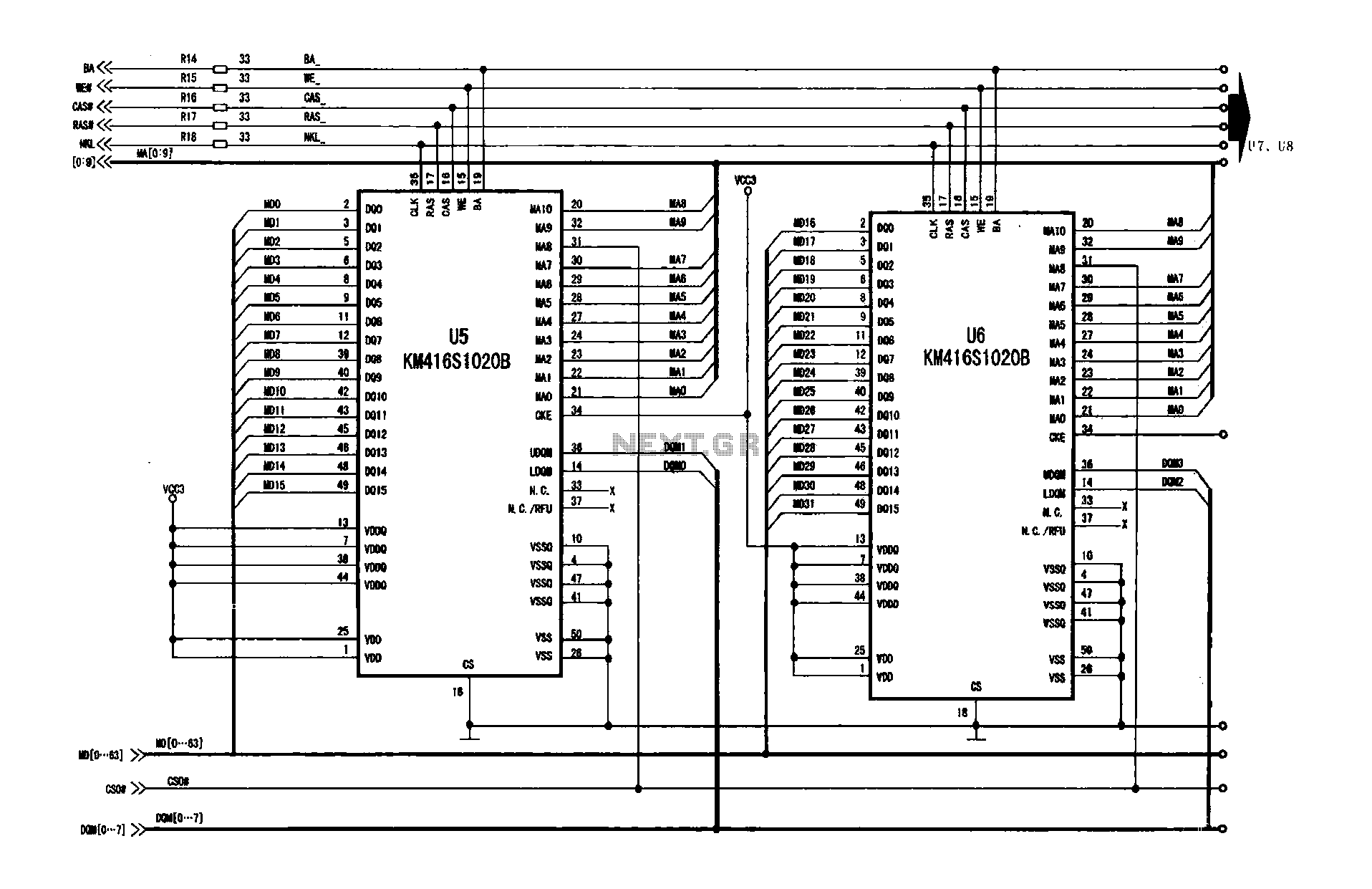
A digital signal processing circuit that operates in conjunction with a memory system for temporarily storing image data. The DPTVT-3D/MV digital processing chip requires four KM416S102 memory units, each providing 16 MB of digital memory. The circuit structure is...
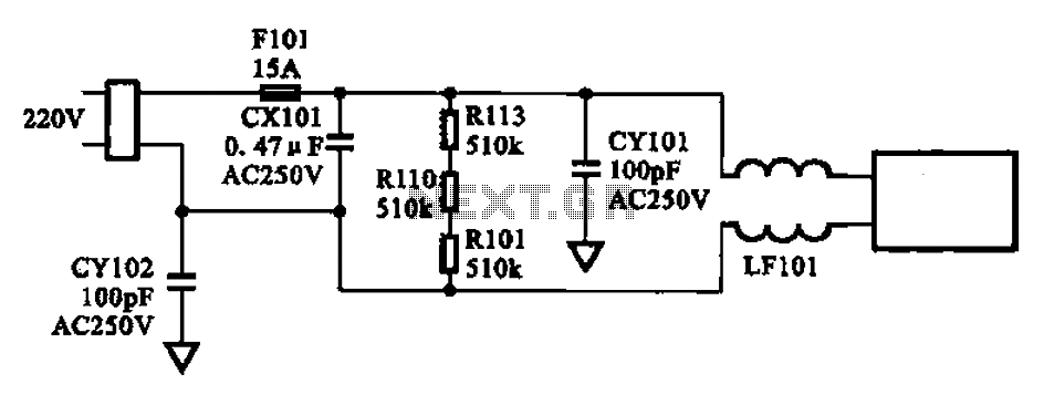
The AC input circuit consists of a fuse (Fl01), a mutual inductance filter (LF101), and filter capacitors (CX101, CY101, CY102), among other components. Its primary function is to filter out noise and pulse interference from the AC circuit, as...
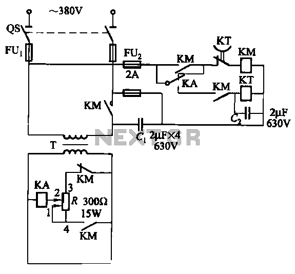
The relays in the AC arc welding machine manage the load through a three-way power circuit, as depicted in Figure 522. The selected relay type is KA, operating at 24V. Additionally, the time relay KT is of the JS7...
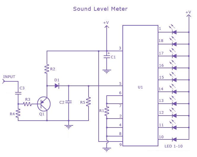
This is a single-chip sound level meter that can be used to display the sound level of an amplifier or simply the sound level from a microphone. The core component of the circuit is the IC LM3915 Audio Level...
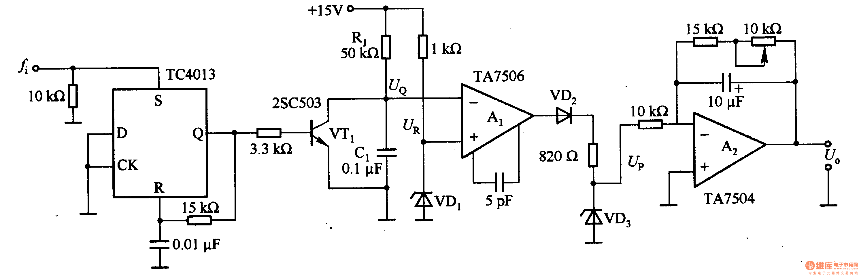
This circuit can convert an input frequency ranging from 0 to 100 Hz into an output voltage of 0 to 10 V. It utilizes the TC4013 monostable multivibrator to shape and amplify the input pulse, which has a width...
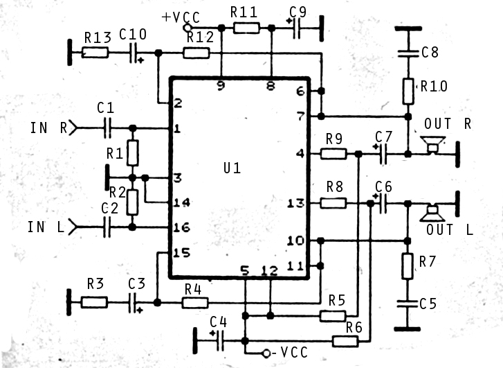
The audio amplifier circuit is highly suitable for home use, particularly with subwoofer or woofer speakers. Commonly referred to as a home amplifier, these audio amplifiers are based on integrated circuits (ICs), specifically the STK series, which includes models...