
Circuit Diagram of Audio Logic Level Probe Composed of 555

The audio logic level probe circuit is designed to provide a visual or audible indication of the logic levels present in digital circuits, specifically those utilizing TTL (Transistor-Transistor Logic) or CMOS (Complementary Metal-Oxide-Semiconductor) technology. The core components of this circuit include a voltage comparator, which is responsible for comparing the input voltage against a predefined threshold. This threshold is crucial for determining whether the input signal is classified as a high or low logic level.
The multivibrator, typically configured as an astable or monostable multivibrator, generates a square wave output based on the input signal from the voltage comparator. This output is then fed into the piezoelectric ceramics (HTD), which convert the electrical signals into audible sound waves. The frequency of the sound produced correlates with the detected logic level, providing an immediate and intuitive method for users to assess the status of the digital circuit.
In operation, when the probe is connected to a TTL or CMOS circuit, the voltage comparator continuously monitors the input voltage. If the voltage exceeds the set threshold, indicating a high logic level, the comparator triggers the multivibrator. The multivibrator then produces a signal that activates the piezoelectric element, resulting in an audible tone. Conversely, if the input voltage is below the threshold, the circuit remains inactive, and no sound is produced.
This circuit is particularly useful in troubleshooting and testing digital circuits, as it allows engineers and technicians to quickly determine the logic state of various points in a circuit without the need for complex measurement equipment. The simplicity and effectiveness of the audio logic level probe make it an invaluable tool in the field of electronics.The above picture is audio logic level probe circuit, which is composed of voltage comparator, multivibrator, and piezoelectric ceramics HTD etc. The latter two constitute audio circuit and the audio frequency is used to assess the TTL or COMOS instrument s electrical level.
When the probe reaches high level, IC-1 sends out signal to make D2 conducted.. 🔗 External reference
Related Circuits
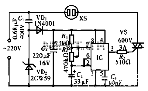
The circuit operates using an integrated circuit (IC) NE555 along with resistors R, RP, and capacitor C3, forming an astable multivibrator configuration. The output from pin 3 of the IC generates a square wave oscillation signal, which is passed...
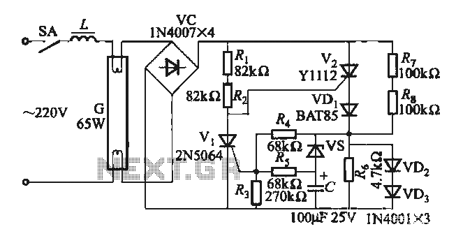
One electronic ballast circuit is depicted in Figure 2-11. This circuit utilizes a specialized fluorescent lamp starter thyristor, SCR Y1112, which is superior to ordinary thyristors due to its ability to maintain a higher current value and dU/dt values....
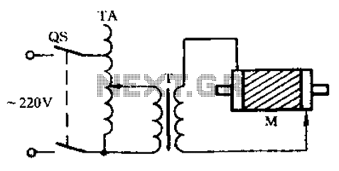
Check the three-phase motor with broken bars as shown in the inspection circuit for the three-phase motor with broken bars. The inspection circuit for a three-phase motor with broken bars is designed to diagnose and evaluate the condition of the...
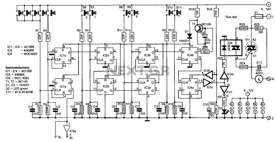
This switch utilizes four CD4013BE dual flip-flops, an inverter, and an optoisolator to control a triac, allowing it to switch a 25-A AC load current. A standard 4x3 telephone keypad is employed for entering a 6-digit code. In the...
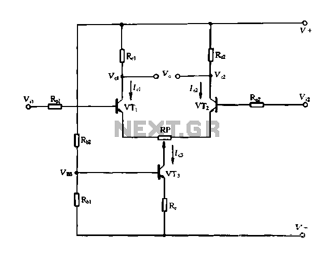
A differential amplifier with a constant current source is illustrated in Figure 1-27. As long as capacitor C3 is maintained at a constant value, capacitors C1 and C2 cannot be simultaneously increased or decreased, preventing voltage drift. The differential...
The NE5532 preamplifier is widely recognized for its excellent performance. It is now being utilized as a small power amplifier. While the general operational amplifier (op-amp) circuit remains similar, there are notable changes in some resistors and capacitors, leading...