
Phase-Controlled Dimmer Circuit

A phase-controlled dimmer is an electronic device that modulates the power delivered to a load by delaying the conduction angle of the AC waveform. The core component in this circuit is a triac, which acts as a switch that can control the flow of current through the load. The operation of the dimmer is based on the principle of phase control, where the triac is triggered at a specific point during each half cycle of the AC waveform.
The circuit typically includes a control circuit that generates a trigger pulse for the triac. This control circuit may utilize a microcontroller or a simple RC timing circuit to determine the delay before the triac is turned on. By adjusting the delay, users can control the brightness of the lamp or the heat output of a heater. For example, a longer delay results in a dimmer light or less heat, while a shorter delay allows more current to flow, increasing brightness or heat output.
It is important to note that this type of dimmer is specifically designed for resistive loads, such as incandescent lamps and heating elements. The dimmer is not suitable for inductive loads, such as transformers or inductive motors, as these can cause the triac to malfunction or operate inefficiently. Universal motors, which have brushes and can operate on AC or DC, are compatible with this type of dimmer due to their resistive characteristics during operation.
In summary, a phase-controlled dimmer provides a simple and effective means of controlling the power to specific types of electrical loads by manipulating the timing of AC waveform conduction through a triac. Proper application and understanding of the circuit's limitations are essential for safe and effective use. A phase-controlled dimmer delays the triac turn-on to a selected point in each successive ac half cycle. Use this circuit only for incandescent lamps, heaters, soldering irons, or universal motors that have brushes.
Related Circuits
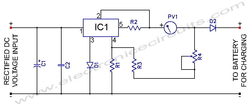
L200 12V Constant Voltage Battery Charger Circuit. This battery charger is based on the L200 regulator IC. The L200 is a five-pin adjustable voltage regulator. The L200 constant voltage battery charger circuit is designed to provide a stable 12V output...
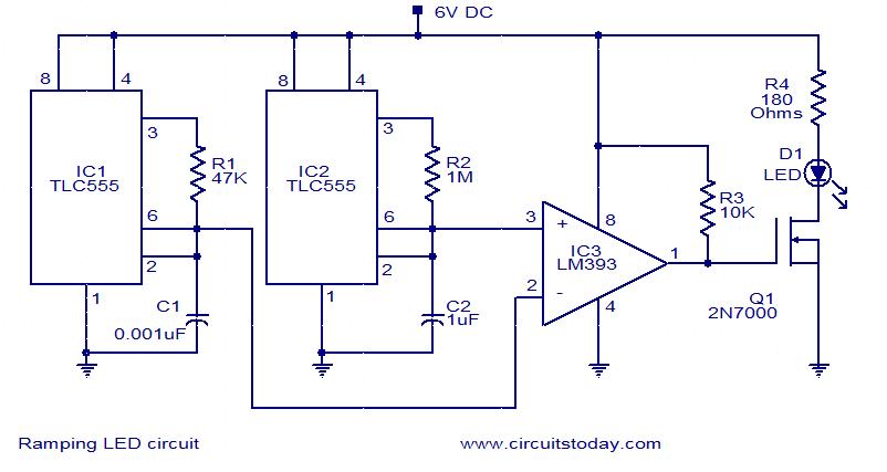
In this circuit, the intensity of the LED varies in a ramping fashion. The circuit comprises three integrated circuits: two 555 timer ICs and one LM393 operational amplifier. IC1 and IC2 are configured as oscillators to generate frequencies of...
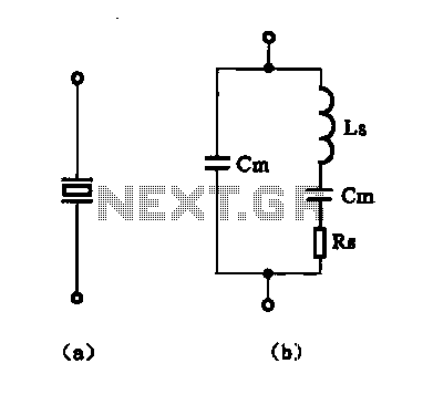
The crystal equivalent RLC circuit is illustrated. The RLC circuit can operate in either a series resonant or parallel resonant configuration. The crystal equivalent RLC circuit is a fundamental electronic circuit that models the behavior of a crystal oscillator. This...
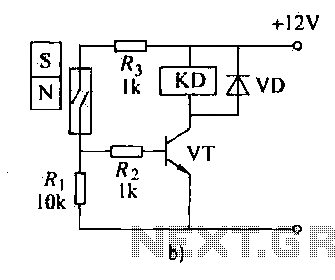
The automatic weapon features a magnetic switch circuit that is simple, reliable, has a low failure rate, and offers good versatility. It can be used to output performance or convert mechanical displacement. The circuit diagram utilizes a Hall switch...
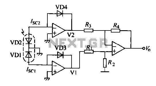
The operation of a semiconductor color sensor can be summarized as follows. The figure illustrates the spectral response curve of two photodiodes that intersect at a specific wavelength. When light of this wavelength is incident on the photodiodes, the...
When the infrared receiver tube PH302 receives a signal from the remote control, the CX20106A selected frequency amplifier outputs a low-frequency signal. The low-level signal charges capacitor C through diodes D and R, causing the negative side potential of...