
Water Level Indicator Circuit

The described circuit operates as a water level detection system utilizing a combination of integrated circuits and discrete components. The circuit's primary function is to monitor the water level relative to the steel rods, which serve as electrodes. The absence of water results in an open circuit condition between the metal can and the rods, leading to no current flow through the circuit based around IC1, which is likely a comparator or operational amplifier.
In this configuration, R5 acts as a pull-down resistor, ensuring that the voltage at the output remains at ground potential when the circuit is inactive. The window comparator formed by IC2A, IC2B, and transistor Q1 is crucial for determining the water level. The comparator checks the voltage levels at pins #2 and #5; when these pins are at zero volts, D3, presumably an LED, will illuminate, indicating the low water level condition.
Once the water level rises and makes contact with the first rod, the input pins #9 to #12 of IC1 are connected to the negative voltage, causing pin #13 to transition to a high state. This change in state can trigger further actions in the circuit, such as turning off D3 or activating additional components to manage the water level, depending on the overall system design.
The use of insulated wooden support for the rods is essential to prevent unintended grounding or short-circuiting, ensuring accurate readings from the water level. The design is likely intended for applications in water tanks, reservoirs, or similar environments where monitoring of water levels is critical for operational efficiency and safety. Overall, this circuit provides a reliable means of detecting water levels, with clear visual feedback through the illumination of D3.When the water-level is below the steel rods, no contact is occurring from the metal can and the rods, which are supported by a small insulated (wooden) board. The small circuit built around IC1 draws no current and therefore no voltage drop is generated across R5.
IC2A, IC2B and Q1 are wired as a window comparator and, as there is zero voltage at input pins #2 and #5, D3 will illuminate. When the water comes in contact with the first rod, pin #13 of IC1 will go high, as its input pins #9 to #12 were shorted to negative by means of the water contact..
🔗 External reference
Related Circuits
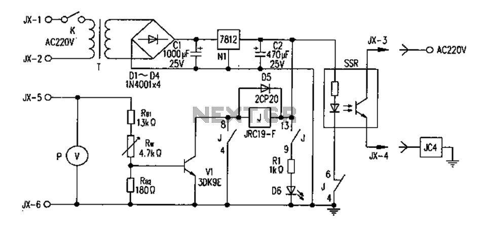
The controller consists of a liquid level sensor, a trigger controller, and a step-down rectifier circuit. The water level detection poles labeled a, b, and c form a bias circuit, functioning as a water level detector with components W1,...
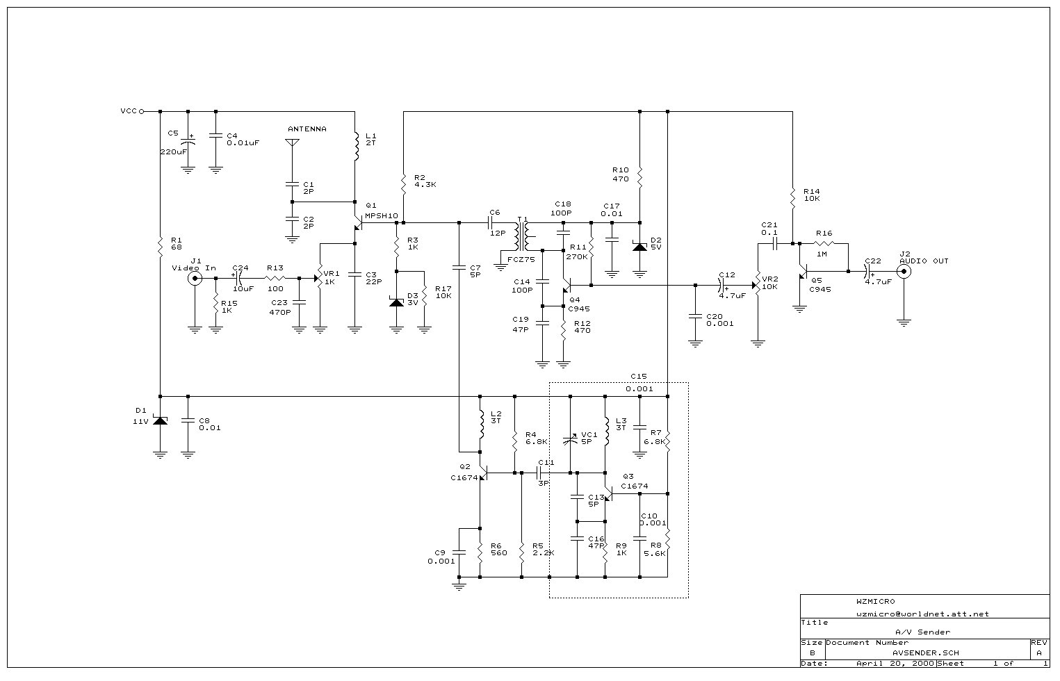
Wireless audio and visual transmission to a TV. The TV functions as a receiver, eliminating the need for a separate monitor. It can also be connected to a VCR or CCD camera, enabling the setup of a remote CCTV...
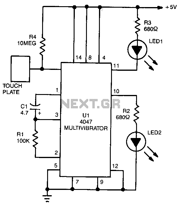
LED1 and LED2 indicators activate and stay illuminated each time the circuit is triggered. During the timing cycle, the Q output at pin 10 of U1 becomes positive when the Q output at pin 11 turns negative. The two...
The FM302E-I-type FM transmitter exciter is utilized in Japan's NEC HPB a 1210 motherboard. It features direct carrier frequency modulation, phase-locked frequency stabilization, and frequency synthesis. The preamplifier (BLF-177 FET) is directly driven by an actuator, achieving a maximum...
The search coil, CI and C2, form a tuned circuit for the oscillator, which is tuned near the center of the broadcast band. Tune a portable radio to a station near the middle of the band, then adjust C2...
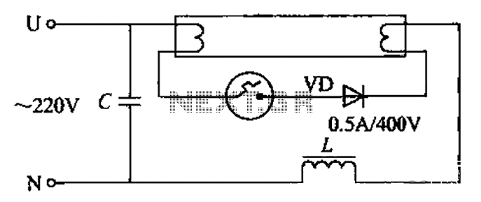
By incorporating a second pull tube into the circuit during the starter ionization phase, the positive half-cycle diode conduction results in an approximate DC current flow. This current is rectified, and due to the small ballast impedance, the instantaneous...