
Water Level Indicator Circuit Schematic

The remote monitoring unit is designed to provide a straightforward solution for level indication in various applications. It utilizes a two-wire configuration, allowing for easy installation and minimal wiring complexity. The device operates on a 9V battery, ensuring portability and flexibility in deployment, especially in locations where mains power is unavailable.
The three-LED level display serves as the primary user interface, providing clear visual feedback on the monitored level. Each LED corresponds to a specific level threshold, enabling users to quickly assess the status of the monitored environment. For example, the first LED may indicate a low level, the second a medium level, and the third a high level, allowing for immediate recognition of critical states.
The circuit design may incorporate a simple voltage divider or a resistive sensing element to detect the level of the monitored substance, whether it be liquid or granular material. The output from the sensing element is processed by a comparator circuit, which drives the LEDs based on the detected level. This approach ensures that the device remains energy efficient, prolonging battery life while maintaining reliable performance.
Overall, this remote monitoring unit is a practical solution for applications requiring real-time level monitoring in a user-friendly format. Its simplicity and effectiveness make it suitable for a range of environments, from industrial settings to home use.Simple, two-wire, remote monitoring unit, Three-LED level display, 9V battery powered The whole project was developed on a friend s request. Its purpose w.. 🔗 External reference
Related Circuits
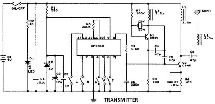
This circuit resembles that of a car radio-controlled toy with seven control functions: forward, forward-left, forward-right, backward, backward-left, backward-right, and stop. Additionally, this radio frequency circuit can be utilized for other electronic circuits that require a simple wireless motor...
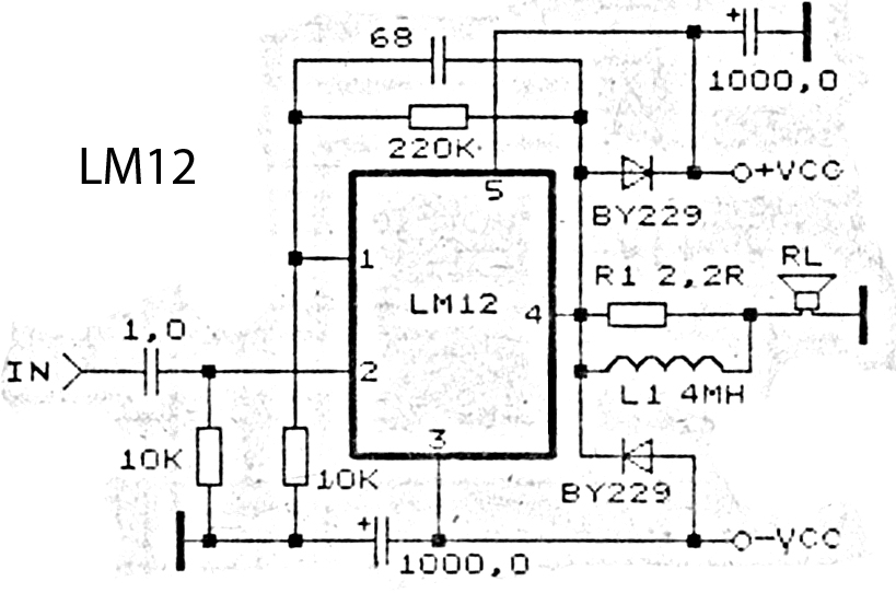
This is an amplifier circuit utilizing the LM12 integrated circuit as the primary amplifier. The amplifier delivers a power output of 150 watts and operates with a load impedance of 4 ohms. It is classified as a high-output power...
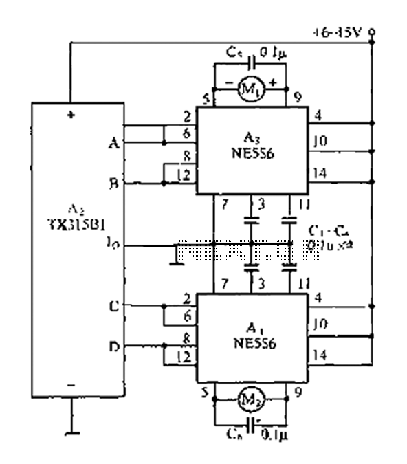
The travel remote control model is represented by a circuit diagram. The NE556 is a dual time base IC that includes two separate circuits, each consisting of a Schmitt trigger circuit. The output control is achieved through the TX315B1,...
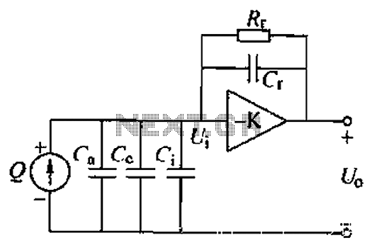
A charge amplifier is an effective device for measuring punch hits. This amplifier utilizes a negative feedback capacitor in conjunction with a high-gain operational amplifier. The amplifier operates with minimal shunt, relying primarily on the feedback capacitor's charge (q...
This circuit activates an alarm when its sensor comes into contact with water. It employs a 555 astable multivibrator that generates a tone of approximately 1 kHz upon water detection. The circuit consists of a 555 timer configured in astable...
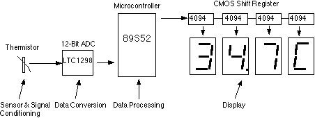
This assignment pertains to the course "Designing Microprocessor Based Instrumentation." The project features a board that utilizes a 12-bit ADC, a C program with digital filtering, and an LED display interface. It achieves a temperature reading sensitivity of 0.1°C....