
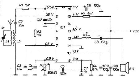
LM12 - High Power Amplifier circuit Schematic Diagram

The LM12 power amplifier circuit is designed to deliver significant audio amplification with high fidelity. The LM12 integrated circuit is known for its robustness and ability to handle high power outputs, making it suitable for demanding audio applications. The circuit configuration typically includes input and output coupling capacitors, feedback resistors, and biasing networks that ensure stable operation across the specified frequency range.
The circuit's power supply must provide a minimum voltage of 9 volts, ensuring that the amplifier operates efficiently without distortion. The center-tapped transformer output of 50 volts allows the amplifier to deliver high output power while maintaining linearity and low distortion. The 4-ohm load impedance is optimal for driving speakers in various audio setups, making this amplifier versatile for both home audio systems and professional sound reinforcement applications.
In terms of performance, the LM12 amplifier circuit is capable of achieving low total harmonic distortion (THD) and a high signal-to-noise ratio (SNR), contributing to a clear and powerful audio output. Proper heat dissipation measures, such as heat sinks and thermal management, should be implemented to prevent overheating during prolonged use, especially at high output levels. Overall, the LM12 amplifier circuit presents a reliable solution for high-power audio amplification needs.This is an amplifier circuit using ic LM12 as the main amplifier. This amplifier has a 150Watt power output and has a 4 ohm impedance. These amplifiers have a classified high output power. The frequency response of 10Hz to 30KHz. Supply Voltage at least 9 Volt and 50 Volt CT. You are reading the Circuits of LM12 - High Power Amplifier circuit And this circuit permalink url it is 🔗 External reference
Related Circuits
This is an enhanced infrared (IR) remote control extender circuit that exhibits high noise immunity, resistance to ambient and reflected light, and an extended operational range of approximately 7 meters between the remote control and the extender circuit. It...
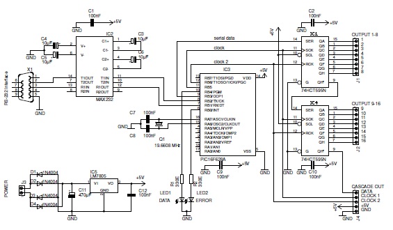
This basic PIC-based RS-232 serial interface can control up to 120 digital TTL outputs. The described circuit utilizes a PIC microcontroller to facilitate communication via the RS-232 protocol, which is a standard for serial communication. The interface primarily serves to...
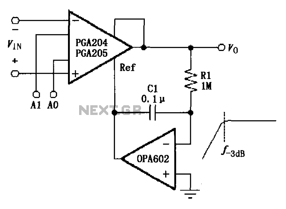
The circuit depicted in the figure features a programmable amplifier utilizing the PGA204/205 operational amplifiers in conjunction with the OPA602. The OPA602 op-amp is configured to establish a feedback reference point, while external components, specifically the capacitor C1 and...
This AM radio receiver circuit utilizes the TDA1083 radio IC, which is suitable for constructing a simple medium frequency (MF) band radio. The schematic operates within a frequency range of 300 kHz to 3 MHz. The circuit is straightforward...

The relay power in the linear circuit is derived from a -120 V bias supply, while the transmit keying output from the Kenwood device is +12 V with a maximum current of 10 mA. A critical component of this...
A typical circuit for welding equipment is illustrated in the following circuit diagram. The turn-on delay can be accurately controlled with Potentiometer P2, allowing for effective discharge management. The welding equipment circuit typically incorporates several key components to ensure proper...