
Motor Bike Headlight Controller Circuit
This circuit design implements an automatic headlight control system for motorcycles, enhancing safety and convenience by ensuring that the headlight operates without manual intervention. The operation begins with the initial stage, where a 220-ohm resistor (R1) and a zener diode (ZD1) are configured to maintain the transistor Q1 in an off state when the motorcycle engine is not running. This configuration draws a minimal current of approximately 2mA, ensuring low power consumption when the system is inactive.
As the motorcycle engine starts and the battery voltage rises above 7.0V, the zener diode ZD1 allows sufficient voltage to turn on transistor Q1, initiating the headlight operation. This transition is critical as it signifies the system's readiness to engage the headlight once the vehicle is in operation.
In the subsequent stage, a second 220-ohm resistor (R2) and another zener diode (ZD2) are used to control transistor Q2. When Q2 is activated, it pulls the base of Q1 down, effectively saturating it and allowing current to flow through the headlight circuit. The configuration ensures that Q1 remains in a fully on state as long as the battery voltage is above the threshold set by ZD2. The Vbe drop associated with Q2 plays a crucial role in this process, as it ensures that Q2 will turn off when the battery voltage drops to approximately 6.7V, thereby preventing the headlight from depleting the battery excessively when the engine is off.
Heat management is a significant consideration in this design, as both transistors Q1 and Q2 will dissipate heat during operation. Therefore, appropriate heat sinks must be installed to prevent thermal overload and maintain reliable operation.
The compact design allows for the circuit to be mounted close to the motorcycle's battery, simplifying the installation process. A single lead connects the circuit to the headlight power feed, streamlining the wiring and enhancing the overall functionality of the motorcycle's lighting system. This automatic headlight control circuit not only improves visibility during rides but also reduces the risk of battery drain when the motorcycle is not in use.This circuit automatically turns a motor cycle`s headlight on and off, independently of both the light and ignition switches, provided the battery is fully charged. The first stage uses the 22O resistor and ZD1 to hold transistor Q1 off while the motor is not running; it draws about 2mA.
Once the battery voltage exceeds 7. 0V during charging, Q1 be gins to turn on. The last stage uses the 22O resistor and ZD2 to turn on transistor Q2, which pulls the base of Q1 down, switching it hard on. In conjunction with the Vbe drop of Q2, ZD2 will turn off Q2 at a battery voltage of about 6. 7V. In practice, this means that the headlight will be on most of the time while the motor is running and charging the battery.
Heatsinks are required for both transistors. The circuit can be mounted adjacent to the battery with a single lead going to the headlight power feed. 🔗 External reference
Related Circuits
Typical segment display LEDs consume around 25 mA for each segment and should be limited to this current with resistors. For a six-digit display to be current limited, at least 42 series resistors are needed. The brightness of the...
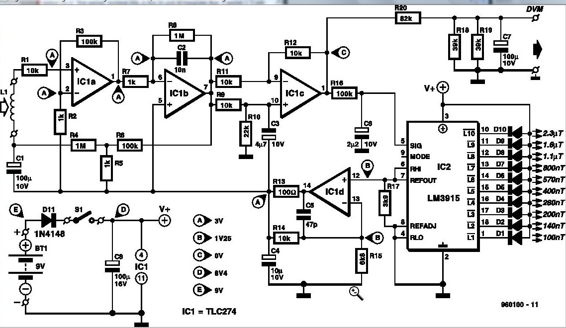
Some experts believe that static magnetic fields (SMFs) may affect the physical well-being of individuals. If one subscribes to this viewpoint, the magnetic-field meter described here will aid in locating sources of SMFs and assessing their strength. These results...
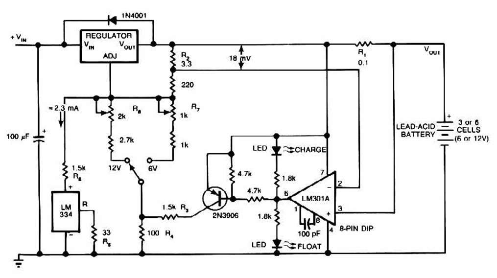
The schematic for this charger is straightforward. It is designed to charge a Gel Cell or other lead-acid types. This simple battery level monitor circuit can indicate the charging process in a 12 Volt lead-acid battery or tubular battery....
This is a beta release schematic. Use at your own risk. The idea is to add this circuitry to a board that already has RAM at address 2000 and an 82C55 I/O chip to provide ports A, B, and...
This signal generator is designed for the realignment of radio receivers. The unit is inexpensive and relatively simple but adequately serves its intended purpose. However, the output is not a pure sine wave, which may make it unsuitable for...
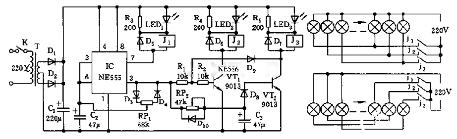
The controller features a buck rectifier circuit utilizing a 555 multivibrator, designed for controlling approximately 220V, 5W low-power parallel lights or 6 to 12V small bulb series. The 555 timer, along with components D3, D4, RP1, and C2, forms...