
water level indicator with

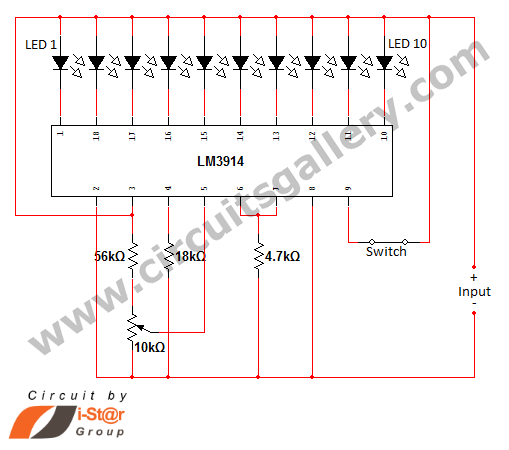
The described circuit operates as a water level indicator and alarm system, utilizing a series of LEDs to provide visual feedback on the water level within a tank. The circuit's operation is contingent on the conductivity of water, which serves as a medium to close or open switches based on the water level.
At the lowest water level, the wires within the tank remain disconnected, leading to an open circuit condition. The 180K ohm resistor connected to the switch pulls the voltage low, ensuring that the switch remains open and all LEDs are off, indicating an empty tank condition.
As the water begins to fill the tank, it bridges the gap between the wire connected to switch S1 and the positive supply, effectively closing the switch. This action activates LED1, providing an initial visual indication of water presence. With further filling of the tank, additional wires connected to subsequent switches or points in the circuit become bridged by the water, causing LEDs 2, 3, and 4 to illuminate in sequence. This gradual lighting of the LEDs serves as an informative gauge for users to monitor the increasing water level.
Upon reaching the full level, the water contacts the base of the BC148 transistor, raising the base voltage and pushing the transistor into saturation. In this state, the transistor allows current to flow through to the buzzer, activating it to signal that the tank is full. To deactivate the buzzer, the user must open the SPST switch, which interrupts the circuit and disables the buzzer alarm.
This design effectively combines simple electronic components to create a functional water level monitoring system, integrating visual indicators with an audible alarm to alert users about the tank's status. The circuit's reliance on the conductive properties of water makes it a straightforward and efficient solution for water level detection and alerting.When the water is empty the wires in the tank are open circuited and the 180K resistors pulls the switch low hence opening the switch and LEDs are OFF. As the water starts filling up, first the wire in the tank connected to S1 and the + supply are shorted by water.
This closes the switch S1 and turns the LED1 ON. As the water continues to fill the tank, the LEDs2, 3 and 4 light up gradually. When the water is full, the base of the transistor BC148 is pulled high by the water and this saturates the transistor, turning the buzzer ON. The SPST switch has to be opened to turn the buzzer OFF. 🔗 External reference
Related Circuits
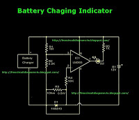
This is a battery charger indicator circuit diagram. When the battery is charging, it is indicated by an LED. This circuit can be used with a 12V battery with a charging current of less than 1A. The battery charger indicator...
This schematic diagram illustrates a 555 IC water level sensor and detector alarm circuit. The circuit is powered by the emitter current of the BC109C transistor. The 555 timer operates as an astable oscillator in this configuration. Under dry...

A circuit design has been conceptualized, and an Assembly code program has been drafted for a three-level mini system. The described circuit design focuses on a three-level mini system, which can be interpreted as a hierarchical structure where each level...
The operating principle of the circuit is very simple. The first LED D1 is placed in series with the resistor R2 and diode D4. An only be lit this LED indicates that the battery is ypofortismeni. For this reason,...
A battery-status indicator circuit is useful for monitoring portable test equipment and similar devices. LED D1 flashes to attract the user's attention, signaling that the circuit is operational, preventing it from being left on unintentionally. The circuit produces approximately...
In various situations, it is necessary to indicate the amount of battery charge using methods such as LED dot displays or LED bar displays. This circuit utilizes the LM3914 integrated circuit to serve as a battery charge indicator with...