
Magnetic Field Sensor Circuit

The magnetic field sensor circuit typically employs a Hall effect sensor, which is sensitive to magnetic fields. The Hall effect sensor generates a voltage output that is proportional to the strength of the magnetic field encountered. This voltage can be processed further to indicate the presence and strength of the magnetic field.
The circuit may include a power supply, often a simple battery or DC source, to provide the necessary voltage for the sensor operation. Additionally, a microcontroller or an operational amplifier may be utilized to amplify the signal from the Hall effect sensor, allowing for more precise readings. The output can be connected to an LED for visual indication or to a microcontroller for further digital processing.
To construct the circuit, the Hall effect sensor should be connected to the power supply, ensuring that the polarity is correct. The output pin of the sensor can be connected to an analog input of the microcontroller if digital processing is intended. Alternatively, a simple resistor-capacitor (RC) filter may be added to smooth the output signal, especially if the circuit is intended to detect varying fields.
For audio frequency detection, the circuit may incorporate a bandpass filter to isolate the desired frequency range, allowing the sensor to respond effectively to changes in the magnetic field at audio frequencies. The design can be expanded with additional components such as a display module to visualize the magnetic field strength or a wireless module for remote monitoring.
Overall, this DIY magnetic field sensor circuit is versatile and can be adapted for various applications, including educational projects, hobbyist experiments, or basic magnetic field detection tasks.This DIY magnetic field sensor circuit is very simple and can detect fixed magnetic fields or fields that are varying at an audio frequency. The unit is no.. 🔗 External reference
Related Circuits
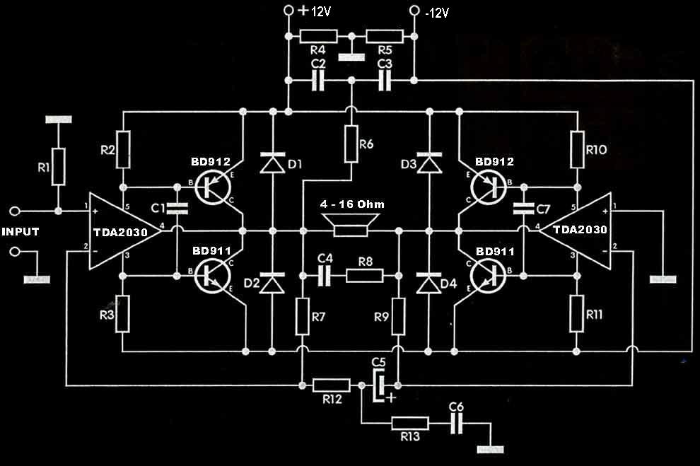
The TDA2030 amplifier circuit is suitable for driving low-frequency subwoofer speakers in home theater systems. The TDA2030 is a monolithic integrated circuit designed for use as a low-frequency class AB amplifier. This TDA2030 amplifier design requires a dual power...
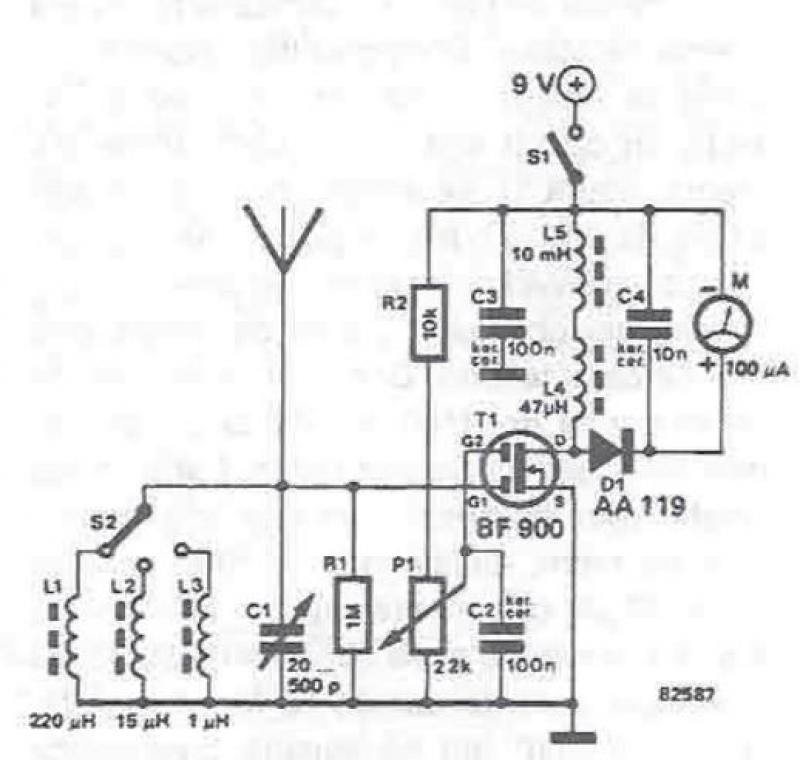
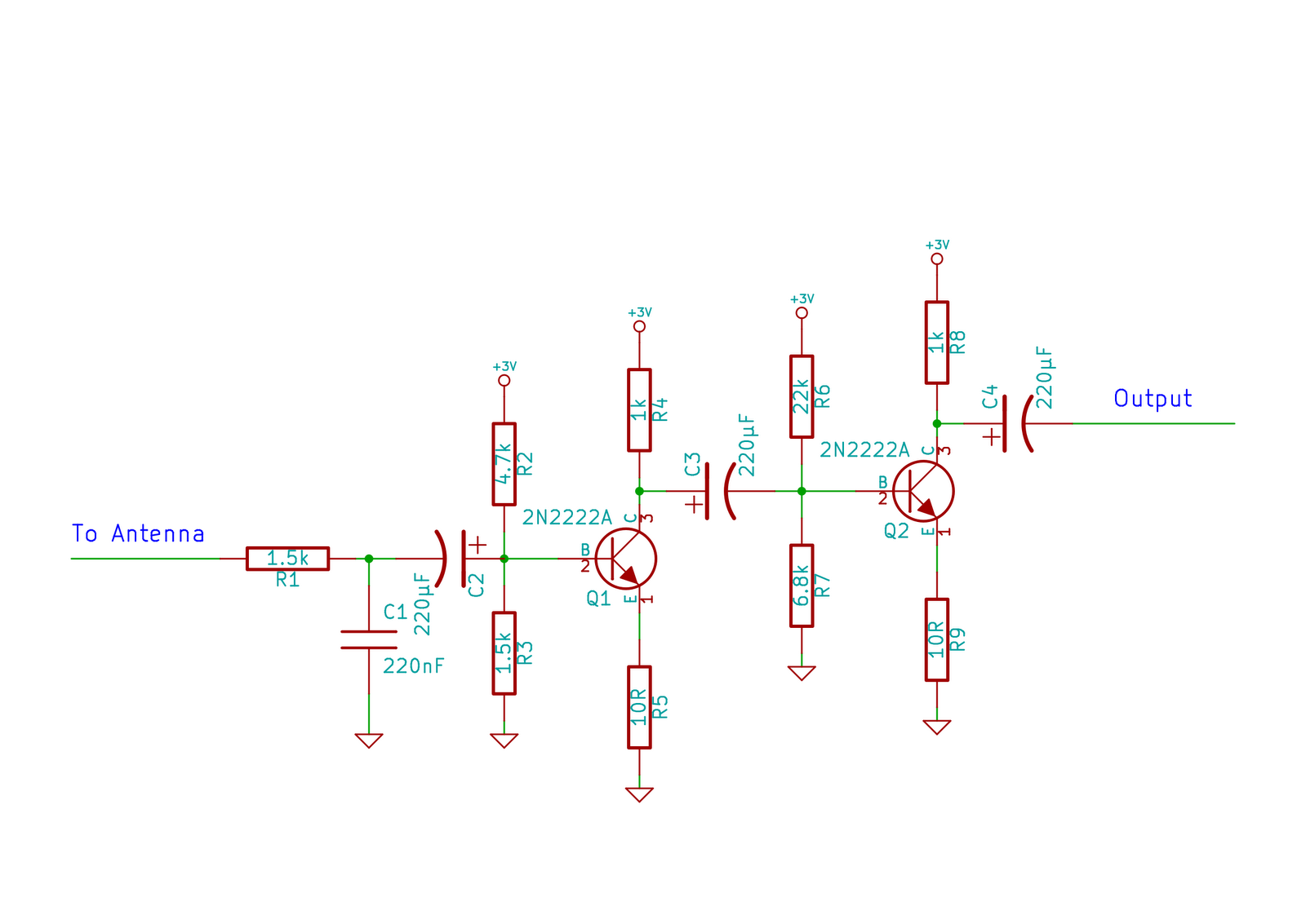
An RF field detector circuit suitable for measuring and verifying the power of antennas and transmitters can be constructed using transistors and common electronic components. This circuit employs a radio frequency transistor, specifically a MOS-FET with two gates. The...
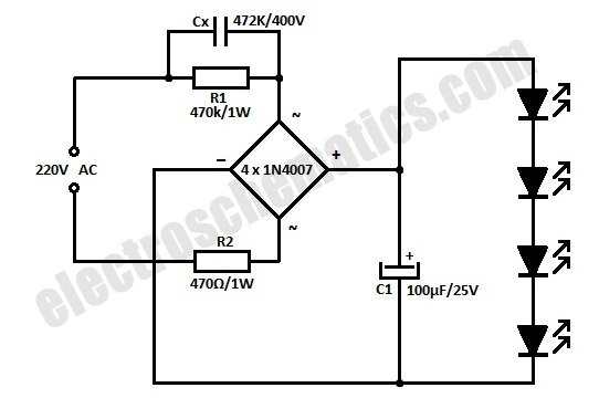
This is a simplified version of a white LED lamp that can be powered directly from the mains. It provides sufficient illumination for reading purposes. Capacitor Cx along... The circuit for the white LED lamp consists of several key components...
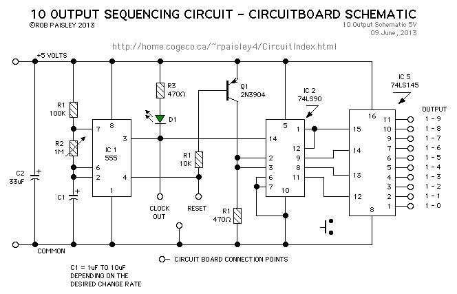
This page presents a circuit featuring twenty open collector outputs that activate sequentially in a continuous, unidirectional loop. The circuit utilizes the 74LSxx family of TTL integrated logic devices. It is designed to drive light-emitting diodes or low current,...
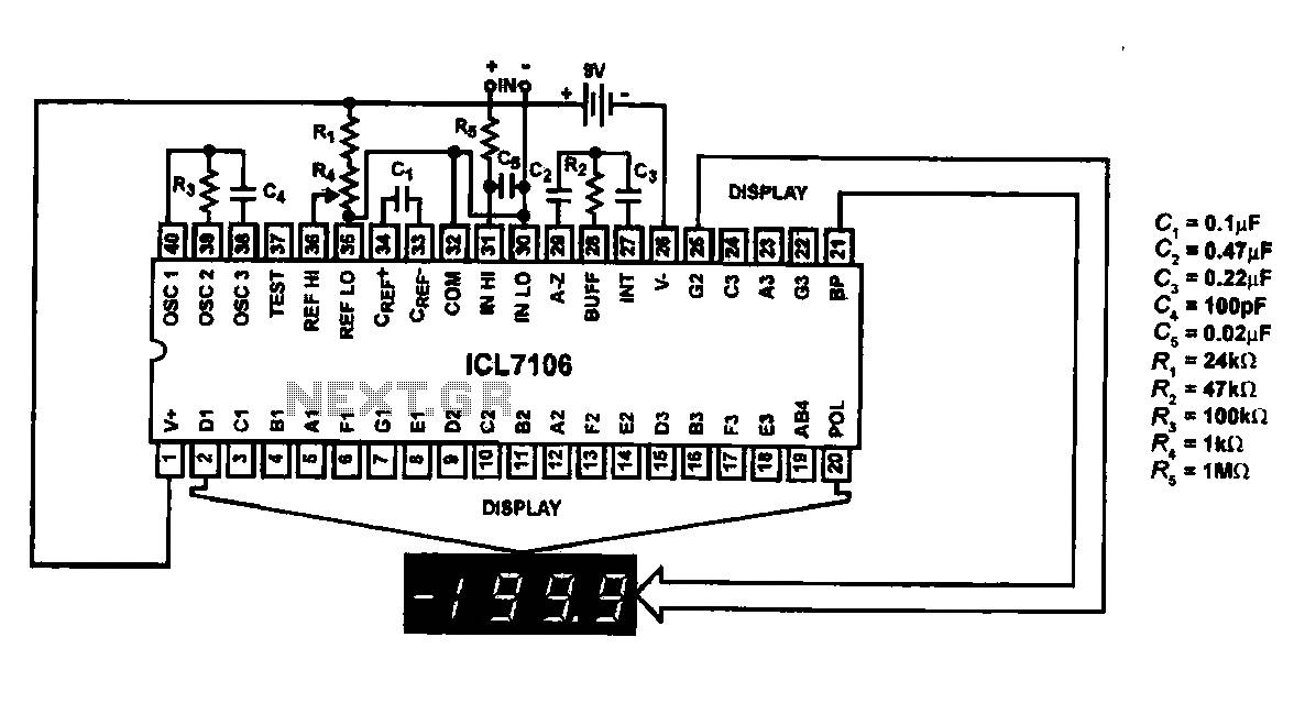
This circuit utilizes the ICL7106 / ICL7107 chip to drive a liquid crystal display (LCD). In this configuration, the ICL7106 / ICL7107 functions as a signal measurement and analog-to-digital (A/D) converter. It detects an analog input signal, amplifies it,...
This circuit does not function as effectively as it could. It was created when the designer had a limited understanding of circuit design. An improved schematic will be developed and posted later, featuring a better design. The schematic indicates...