
The proximity switch circuit with integrated magnetic field sensor HMC1001

The proximity switch circuit utilizes the HMC1001, a highly sensitive magnetic sensor, which detects the presence of a magnetic field. The operational amplifier (AMP04) is configured in a comparator mode to compare the output voltage from the HMC1001 with a reference voltage.
In this configuration, when the magnet is positioned within the specified range (6mm to 12mm) of the HMC1001, the MR bridge generates an output voltage of 30mV. This voltage is sufficient to exceed the threshold set by the operational amplifier's reference input, resulting in a change in the output state of the comparator. The output of the operational amplifier can then drive an LED, indicating the detection of the magnetic field.
The circuit may include additional components such as resistors to set the reference voltage and capacitors for stability and noise filtering. The LED serves as a visual indicator, illuminating when the magnetic field is detected, providing a clear and immediate response to the presence of the magnet. This circuit is applicable in various automation and sensing applications, where proximity detection is essential for system operation.As shown in figure, the proximity switch circuit is composed of HMC1001, operational amplifier (AMP04) and light emitting diode (LED). The operational amplifier is used as a comparator. When you move magnet with length being 6mm~12mm to HMC1001 in a predetermined position, the output voltage of MR bridge will reach 30mV, then the comparator flips, and output..
🔗 External reference
Related Circuits

The system consists of a MAX1463 precision pressure detection circuit block diagram. The output voltage from the bridge pressure sensor is connected to the MAX1463 inputs IN1+ and IN1-. Controlled by a CPU, the pressure signal undergoes nonlinear calibration...

This is the circuit diagram of an audio/video modulator. The circuit converts audio and video signals into a UHF TV signal. It is designed to connect a video signal originating from a camera or other video source to a...

The Coship CDVB3188V receiver features a switching power supply circuit similar to the CDVB3188C model. The circuit includes several key components: an AC input circuit, an anti-jamming filter circuit, a complete flow filter circuit, and a switching oscillation circuit....

In this multivibrator circuit, frequency and pulse width can be separately controlled by using steering diodes (1N914) and two potentiometers. This multivibrator circuit utilizes steering diodes, specifically the 1N914 type, to enable independent control over both the frequency and pulse...
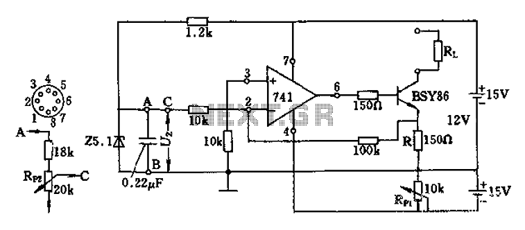
The Darlington transistor circuit BSY86 produces a large output current, with a maximum limit of 150 ohms. The output current is adjustable via resistor R and the RP1 potentiometer, maintaining constancy regardless of the load resistance Rl. The potentiometer...

Similar to the initial two Hijack Alarms, this circuit is designed to activate if a door is opened while the ignition is switched on. After a delay of several minutes, allowing the thief to move a safe distance away,...