
water pump relay controller circuit schematic

The circuit operates on a simple principle of level detection using two sensors, which are strategically positioned at different heights within the water reservoir. The shorter sensor is designed to detect when the water level is sufficiently high, while the longer sensor detects when the water level is critically low.
The integrated circuit (IC1C) plays a crucial role in processing the signals from the sensors. It monitors the state of the sensors continuously. When the water level drops below the longer sensor, the output at pin #10 of IC1C goes low, indicating a low water condition. This state is maintained until the water rises to the level of the longer sensor. Once the water touches the longer sensor, the output remains low until the shorter sensor is activated, indicating that the water level is adequate.
When the shorter sensor is activated, the output of IC1C transitions to high. This change in state triggers transistor Q1 to conduct. Q1 acts as a switch, allowing current to flow to the relay coil. The relay, once energized, closes its contacts and powers the water pump, which begins to fill the reservoir or well.
The relay is an essential component in this circuit as it provides electrical isolation between the low-voltage control circuit and the high-voltage water pump circuit. This ensures safe operation and prevents damage to sensitive electronic components.
Additionally, the circuit may include protective features such as diodes to prevent back EMF from the relay coil from damaging the circuit components when the relay is de-energized. Proper sizing of the relay and pump according to the application requirements is also critical to ensure efficient operation of the system.
In summary, this automatic water level control circuit effectively manages the operation of a water pump based on predetermined water levels, ensuring that the reservoir or well maintains an appropriate water supply without manual intervention.By means of a Relay, employed to drive a water pump, this circuit provides automatic level control of a water reservoir or well. The shorter steel rod is the ""water high"" sensor, whereas the longer is the ""water low"" sensor. When the water level is below both sensors, IC1C output (pin #10) is low; if the water becomes in contact with the longer sensor the output remains low until the shorter sensor is reached.
At this point IC1C output goes high, Q1 conducts, the Relay is energized and the pump starts operating.. 🔗 External reference
Related Circuits
This project automates home appliances via a Bluetooth-enabled PC. A USB Bluetooth adapter is utilized on the PC side, while a Serial Bluetooth module is employed for communication. This project involves the integration of a Bluetooth-enabled PC with home appliances...

This circuit is designed for lamp dimming and similar applications. It requires only one RC phase lag network. To prevent the hysteresis (or "snap-on") effect, the capacitor is reset to approximately 0 volts at the end of every positive...
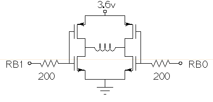
Drive a small (3.6V, <1A) brushed motor bidirectionally with a PIC microcontroller (MCU). The available space is extremely limited, so a single 3.6V power supply will be used for both the motor and the PIC, with minimal drive circuitry required. There is no dedicated motor driver IC that operates at this low voltage, making a discrete H-bridge the most suitable drive arrangement. The NXP PMV30UN and PMV32UP have been identified as suitable N-type and P-type drive MOSFETs. Since both the PIC and the motor share the same power supply, it is questioned whether it is possible to eliminate the usual driving circuitry for an H-bridge and connect the transistors directly to the MCU pins. Potential pitfalls of this approach should also be considered. To design a bidirectional motor drive circuit using a PIC microcontroller and a discrete H-bridge configuration, the following considerations must be taken into account. The H-bridge consists of four MOSFETs arranged in a configuration that allows current to flow through the motor in either direction, enabling bidirectional control. The NXP PMV30UN and PMV32UP MOSFETs are suitable candidates due to their low on-resistance and capability to operate at the required 3.6V supply voltage. The connections between the PIC MCU and the MOSFETs should be made with consideration of the gate drive requirements. Directly connecting the MOSFET gates to the MCU pins can be feasible, but it is essential to ensure that the MCU can provide sufficient gate drive voltage to fully turn on the MOSFETs. A typical threshold voltage for these MOSFETs is around 1V, so the output high level from the PIC should exceed this threshold to ensure efficient operation. It is also critical to incorporate pull-down resistors on the gate pins to prevent the MOSFETs from floating when the MCU is in a high-impedance state. This will help avoid unintended motor activation. Additionally, using gate resistors can help dampen any oscillations and limit inrush current during switching, which could potentially damage the MOSFETs or the MCU. Another consideration is the back EMF generated by the motor when it is switched off or when changing direction. This can induce voltage spikes that may damage the MCU or the MOSFETs. To mitigate this risk, flyback diodes should be placed in parallel with each MOSFET to provide a path for the back EMF, ensuring safe operation of the circuit. Thermal management is also a critical aspect of the design. Although the MOSFETs are rated for low on-resistance, continuous operation near their current limits can lead to significant heat generation. Adequate heat dissipation measures, such as heat sinks or thermal pads, should be considered. In summary, while it is possible to connect the MOSFETs directly to the MCU pins, careful attention must be given to gate drive requirements, protection against back EMF, and thermal management to ensure reliable and efficient operation of the bidirectional motor drive circuit.
It is often necessary to configure a voltage regulator integrated circuit (IC) to provide a higher output voltage than that established by the regulator alone. One method to achieve this is by connecting the common terminal to the midpoint...
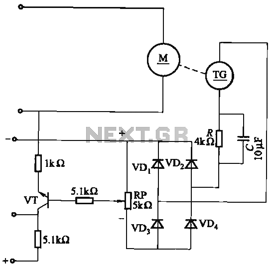
The capacitor C is part of the speed differential negative feedback system. The adjustment potentiometer RP allows for changing the amount of negative feedback. Both components can be utilized simultaneously within the circuit. The voltage (or speed) will only...
The core of this drum machine is based on an electronic drum stick. Swinging the stick produces drum sounds, specifically three sounds: snare, bass drum, and hi-hat. When the stick is swung, it plays a snare sound. There are...