
Water Pump Relay Controller Circuit Schematic

The circuit design employs a relay to control the operation of a water pump based on the water level detected by two sensors. The shorter sensor, positioned at the high water mark, and the longer sensor, at the low water mark, provide critical feedback to the integrated circuit (IC1C). The logic within IC1C determines the state of the pump based on the water level detected by these sensors.
Initially, when the water level is low, both sensors do not make contact with the water, resulting in a low output from IC1C. As water fills the reservoir, it first contacts the longer sensor, but the output remains low until the shorter sensor is activated. The transition of IC1C to a high output triggers Q1, which energizes the relay, activating the pump. This action begins to lower the water level in the reservoir.
While the pump operates, the water level will eventually drop below the shorter sensor, but the output of IC1C remains high due to the feedback from IC1B, allowing the pump to continue functioning until the water level reaches the longer sensor. At this point, the output of IC1C returns to low, signaling the pump to stop.
The inclusion of an optional switch, SW1, allows for versatility in operation. By connecting R3 to pin #11 of IC1D, the circuit can be reconfigured such that the pump operates in reverse. In this mode, the pump will start when the water level is low and stop when the reservoir is full, allowing for the filling of the reservoir instead of its emptying.
This configuration provides a reliable solution for automatic water level management, ensuring efficient operation of the pump while also allowing for flexibility in its intended use. The use of feedback mechanisms within the integrated circuits ensures that the system reacts appropriately to changes in water level, maintaining the desired operational parameters.By means of a Relay, employed to drive a water pump, this circuit provides automatic level control of a water reservoir or well. The shorter steel rod is the water high sensor, whereas the longer is the water low sensor. When the water level is below both sensors, IC1C output (pin #10) is low; if the water becomes in contact with the longer
sensor the output remains low until the shorter sensor is reached. At this point IC1C output goes high, Q1 conducts, the Relay is energized and the pump starts operating. Now, the water level begins to decrease and the shorter sensor will be no longer in contact with the water, but IC1C output will be hold high by the signal return to pin #5 of IC1B, so the pump will continue its operation.
But when the water level falls below the longer sensor, IC1C output goes low and the pump will stop. SW1 is optional and was added to provide reverse operation. Switching SW1 in order to connect R3 to pin #11 of IC1D, the pump will operate when the reservoir is nearly empty and will stop when the reservoir is full. In this case, the pump will be used to fill the reservoir and not to empty it as in the default operating mode.
🔗 External reference
Related Circuits
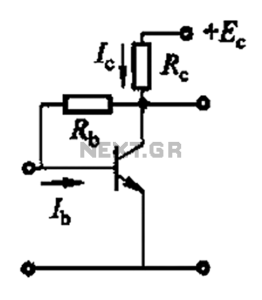
Basic reference bias circuit using a transistor with negative voltage feedback. The basic reference bias circuit utilizing a transistor with negative voltage feedback is designed to provide a stable output voltage or current that is largely independent of variations in...
Color sensing using a camera and a sufficiently powered processor that runs image histogram logic (or similar algorithms) can reliably determine the presence of specific colors. However, alternatives that are significantly more cost-effective for detecting the presence or absence...
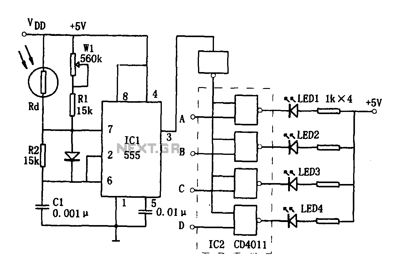
The brightness display circuit consists of a light-sensitive sensor, an oscillation circuit, and an LED display circuit. The light-sensitive sensor is a photosensitive resistor (Rd). The multivibrator is composed of Rd, R1, W1, R2, and C1, along with a...
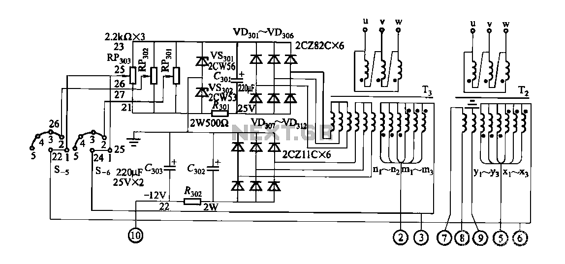
FGDF-3 is a three-phase low-temperature iron plating power supply circuit, while the KGDF-3 is a single-phase low-temperature iron plating power supply device that encompasses all the characteristics of the power supply unit. This design allows for an even distribution...
This is a HiFi pre-amplifier circuit diagram with low noise output. It offers a very wide frequency range from approximately 10 Hz to 100 kHz, which enhances audio performance. The HiFi pre-amplifier circuit is designed to amplify weak audio signals...
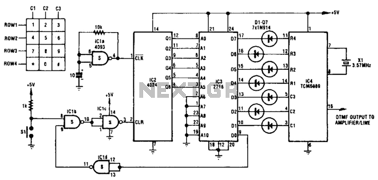
This circuit utilizes inexpensive, commonly available components to generate a precise dial tone for telephone applications. The Intel 82C54 timer-counter (U1) produces square wave signals at frequencies of 350 Hz and 440 Hz, which are subsequently filtered by resistors...