
Waveform Generator with ICL 8038CCPD

The described circuit employs a 14-pin Dual In-Line Package (DIL) integrated circuit (IC) designed for waveform generation. This versatile IC can produce multiple waveform types, including sine, square, triangular, sawtooth, and pulse, making it suitable for various applications such as signal testing, modulation, and audio synthesis.
The frequency output of the circuit can be finely tuned across a broad range from 0.001 Hz to 1 MHz, allowing for both low-frequency and high-frequency applications. The implementation of frequency modulation and sweeping capabilities enhances the circuit's functionality, enabling dynamic changes in frequency based on external voltage inputs. The frequency can be programmed digitally using external resistors or capacitors, providing flexibility in setting the desired output characteristics.
The circuit's user interface includes several components for waveform selection and control. SW1 acts as the range switch, allowing the user to select different frequency ranges for output. SW2 is designated for waveshape selection, enabling the user to choose between the various waveform types available. The output level is adjustable via VR4, which provides control over the amplitude of the generated signal. The frequency control is managed by VR3, allowing for precise adjustments to the output frequency.
Additionally, VR1 and VR2 are critical for fine-tuning the circuit's performance, specifically for minimizing distortion in the sine wave output. Proper adjustment of these variable resistors is essential to ensure high fidelity and accuracy in waveform generation, particularly for applications that require clean and precise sine wave outputs.
Overall, this circuit represents a comprehensive solution for generating a variety of waveforms with high stability and accuracy, making it an invaluable tool in electronic testing and experimentation.That circuit is based on a 14-pin DIL IC capable of producing sine, square, triangular, sawtooth and pulse waveforms of high accuracy and stability. The frequency may be selected to be from 0.001Hz to 1Mhz, Frequency modulation and sweeping can be accomplished with an external voltage and the frequency can be programmed digitally by resistors or capacitors.
Sweep range can be up to 40:1 or 1000:1 with a little less quality.
The circuit shows a sine, triangle and square wave generator. SW1 is the range switch, SW2 sets the waveshape, VR4 sets the output level and VR3 is the frequency control. VR1 and VR2 should be adjusted to give minimum distortion of sine wave.
Related Circuits
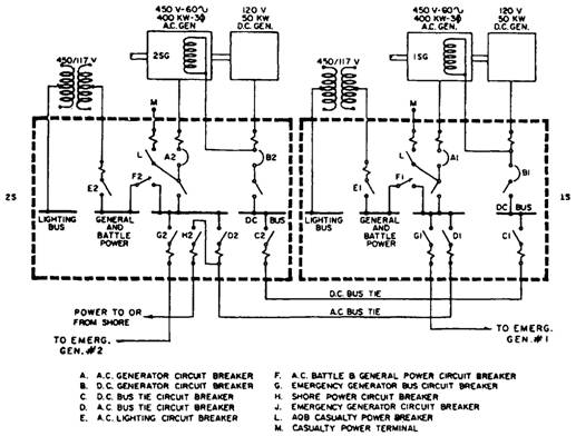
A single-line diagram of the ship's service generator and switchboard connections for a destroyer. Components include a resistor, capacitor, transistor, and others. The single-line diagram serves as a simplified representation of the electrical connections and components within the ship's service...
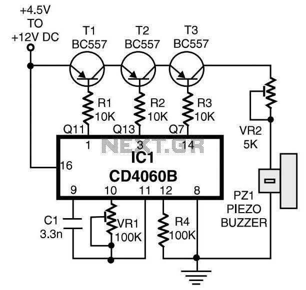
This project is designed to enhance security for personal belongings left unattended on a beach towel, in an office, or workshop setting. It utilizes a compact circuit powered by standard primary cells or rechargeable batteries to generate a low-energy,...
This bell ring generator utilizes the MC14106 or 40106 hex Schmitt inverter IC to produce a dual-tone ringing sound akin to that of standard doorbell units. The circuit design of the bell ring generator is centered around the MC14106 or...
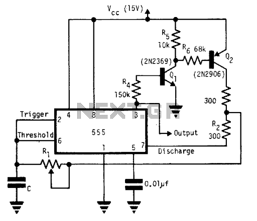
A single timing resistor ensures that the output is a square (50% duty cycle) wave at all frequency settings. Any 555 type of chip will do the job. The circuit utilizes a 555 timer IC configured in astable mode to...
Join the forum discussion on this post. This is a simple home telephone ringtone generator circuit built using only a few electronic components. It generates a simulated telephone ringtone and requires only a DC supply. The home telephone ringtone generator...
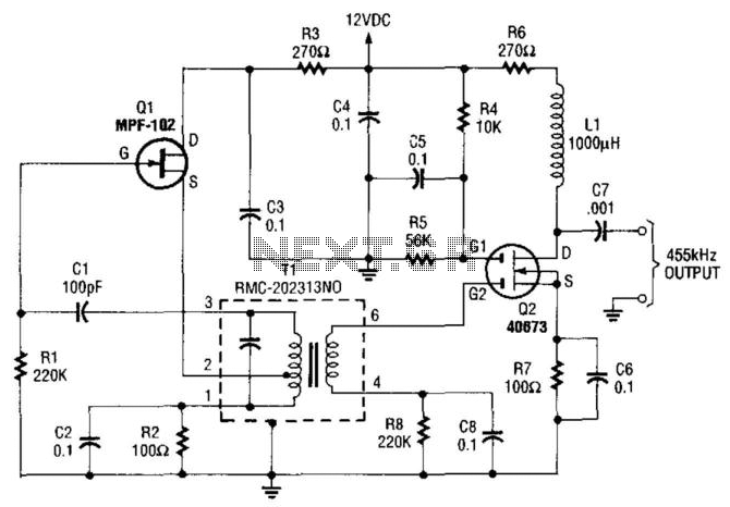
An MPF102 FET oscillator drives a dual-gate MOSFET buffer. The MPF102 is configured as a Hartley oscillator. If desired, an audio voltage can be coupled to the junction of R4, R5, and C5 with an extra coupling capacitor (~1...