
Bells Ring Generator using MC14106 or 40106 Hex Schmitt Inverter IC

The circuit design of the bell ring generator is centered around the MC14106 or 40106 hex Schmitt inverter IC, which is known for its ability to provide stable and noise-immune switching. The dual-tone output is achieved by configuring two of the inverters to operate in an astable multivibrator mode, generating square wave signals at different frequencies. The output frequencies can be adjusted by varying the resistor and capacitor values connected to the inverters.
To construct the circuit, the following components are typically required: the MC14106 or 40106 IC, resistors, capacitors, and a speaker or piezo buzzer for sound output. The resistors determine the timing characteristics of the oscillators, while the capacitors influence the frequency of oscillation.
The circuit can be powered by a standard DC power supply, ensuring that the voltage remains within the operating limits of the IC. Additionally, a diode may be included to protect the circuit from potential back EMF generated by the speaker or buzzer when it is switched off.
Overall, this bell ring generator circuit can be implemented in various applications beyond doorbells, such as alarms and notification systems, providing versatility in sound generation. The dual-tone feature enhances the auditory signal, making it more distinguishable and pleasant to the ear. Proper layout and component selection are crucial for ensuring optimal performance and reliability of the circuit.This Bells Ring Generator using MC14106 or 40106 Hex Schmitt Inverter IC generates a dual-tone bells ringing similar to most door-bell units.. 🔗 External reference
Related Circuits
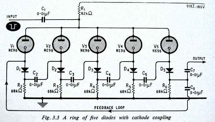
The above shows a home-built digital clock that utilizes Nixie tubes for display. Unlike most contemporary Nixie clocks, this design does not employ transistors or integrated circuits for driving the tubes. Instead, the driving logic is constructed using neon...
An Inverter is a device that converts 12 volts d.c to 120 volts a.c., which is what we use in our homes. This project will handle about 300 watts, which is perfect for lights, small T.V.s and radio equipment....
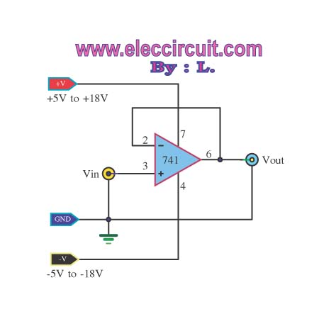
The buffer operational amplifier (op-amp) circuit is utilized for coupling two circuits together. It functions as a unity gain follower, also known as a voltage follower, which is employed to transfer or replicate a voltage from one circuit to...
This circuit generates sine, square, and triangle waves ranging from 0.1 Hz to 1 MHz. It includes a counter that measures the frequency of the function generator or an external signal with a peak-to-peak voltage of a few volts,...

The circuit illustrated below represents a simple thermometer circuit based on the LM335 temperature sensor. This circuit comprises two main components: the LM335 sensor and its adjustment circuitry. The output from the LM335 generates a voltage of 10 millivolts...
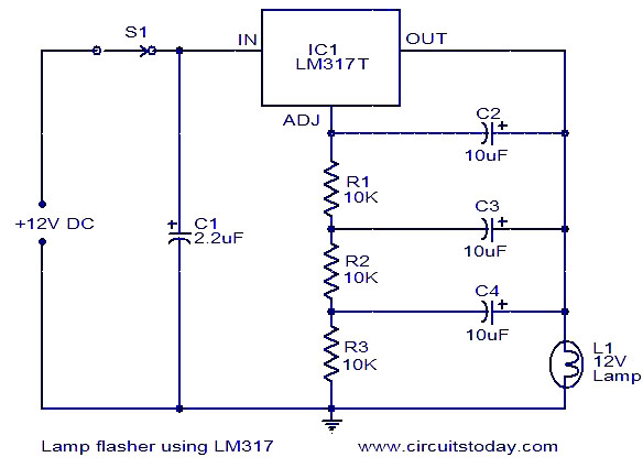
This document describes a lamp flasher circuit utilizing the adjustable voltage regulator IC LM317T. The LM317 can supply a maximum current of 1A, making it suitable for use with lamps up to 12W. This type of circuit has significant...