
Telephone ringtone generator circuit

The home telephone ringtone generator circuit is designed to produce an audible ringing tone that mimics the sound of a traditional telephone. The circuit typically consists of a few essential components, including a microcontroller or timer IC, resistors, capacitors, and a small speaker or buzzer.
At the heart of the circuit, a timer IC such as the NE555 may be utilized in astable mode to create a square wave output. This output oscillates at a frequency that corresponds to the desired ringtone sound, which is usually around 1 kHz to 2 kHz. The frequency can be adjusted by changing the values of the resistors and capacitors connected to the timer IC.
The output from the timer IC is then fed to a transistor, which acts as a switch. The transistor amplifies the signal to drive a small speaker or buzzer capable of producing sound. The speaker is connected in such a way that it converts the electrical signals into audible sound waves, simulating the ringing of a telephone.
To power the circuit, a DC supply, typically ranging from 5V to 12V, is used. The simplicity of this circuit allows for easy assembly on a protoboard or PCB, making it suitable for hobbyists and electronics enthusiasts. Additionally, variations of this circuit can be implemented to include features such as adjustable volume or different ringtone patterns by incorporating additional components like potentiometers or more advanced microcontrollers.
Overall, this ringtone generator circuit serves as an excellent project for those looking to explore basic electronics and sound generation techniques.Join the forum discussion on this post This is a simple home telephone ringtone generator circuit which is built with applying only several electronic components / parts. It generates simulated telephone ringtone and requires only DC supply.. 🔗 External reference
Related Circuits
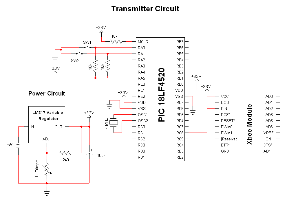
The advantage of these compact Xbee modules is that they handle most of the complex tasks. The transmitter and receiver circuits are both straightforward. The primary components in the circuit include the Xbee Modules, PIC 18LF452, and LM317. Both...
In electronic technology, the triode utilizes a variety of general components and parts. The parameters of the triode and numerous electrical parametric measurement schemes are closely related to measurement results. Therefore, in electronic design, the base pin, typological judgment,...
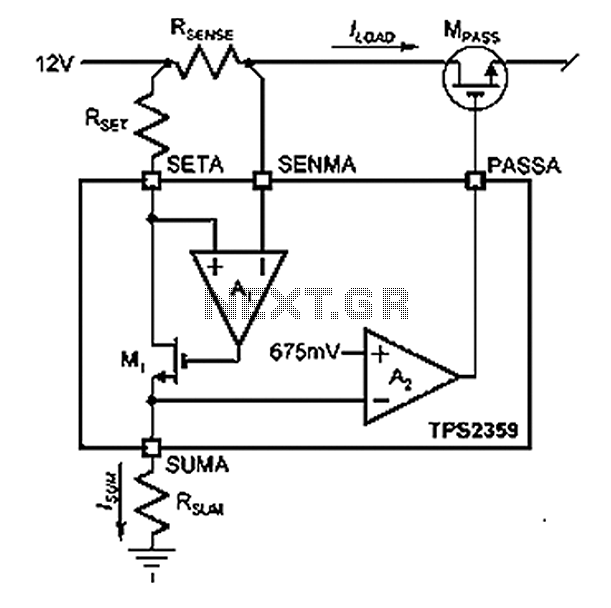
Amplifier A1 utilizes the voltage across the sense resistor sensors to monitor the load current ILOAD. The power management channel employs a similar circuit, with the distinction of integrating resistors RSENSE and RSET. Amplifier A1 is configured to measure the...
Normally the base of a cordless phone has an adaptor and the handset has Ni-Cd cells for its operation. The base unit becomes inoperative in case of power failure. In such conditions, it is better to provide a backup...
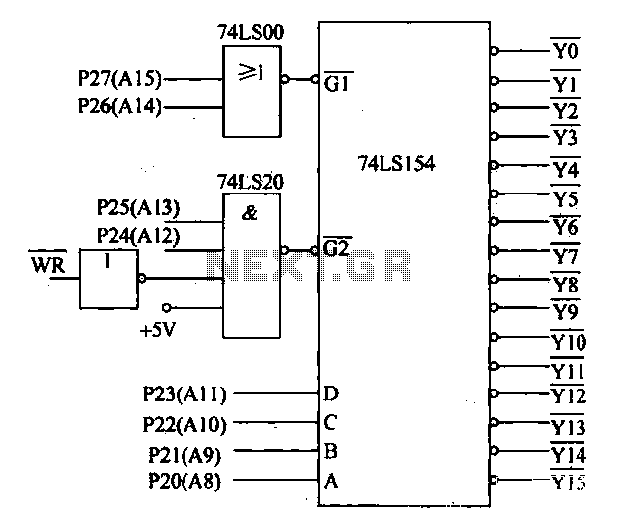
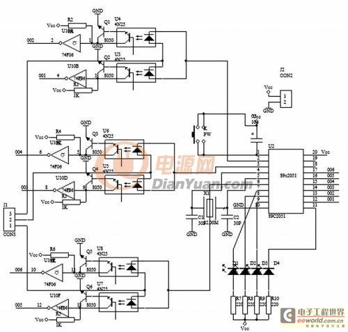
Decoding circuit: To ensure proper functionality of various interfaces, the system must assign IP addresses to all ports. Based on the number of system interfaces, it utilizes the 74LS154 decoder, which can translate up to 16 addresses. The interface...
The Zener diode may not be providing sufficient current in its breakdown state to activate the transistor. Removing resistor R2 did not resolve the issue. The Zener's voltage selection could be too high, potentially preventing it from regulating the...